STL: French Cleat Halter Halter
In diesem YouTube Video French Cleat Halter Halter zeige ich eine Möglichkeit, um Objekte, die an eine French Cleat Wand gehängt werden, zu fixieren bzw. “festzuhalten”. Deswegen der Titel “French Cleat Halter Halter”. Die vorgestellte Lösung lässt sich aus Holz bauen, fräsen, lasern oder drucken. Hier könnt ihr die STL zum 3D Selberdrucken, die DXF zum Fräsen oder Lasern und einen Bemaßungsplan als PDF runterladen.

WICHTIG! Das Erstellen von Anleitungen, Plänen und CAD-Modellen nimmt richtig, richtig, riiiiiichtig viel Zeit in Anspruch. Das können Stunden, Tage oder gar Wochen sein. Wirklich. Ich würde mich daher enorm freuen, wenn du meine Aktivitäten mit einem kleinen Dankeschön würdigst. Hier unten kannst du dir aussuchen, welchen Weg du gehen möchtest. Ich sage schonmal VIELEN DANK!
| Gibt nix, will nur die Dateien haben. |

How to convert 3MF files to stl format on a Lin*x machine (including Mac)
If you need to convert a 3MF file to STL format you may find that there is no really simple solution. I found this very useful blog post by Zebethyal that describes how the command line tool 3mf2stl by Charles Shapiro can be compiled on a Mac to convert 3MF files to STL format. The required steps in all brevity:
- Install Homebrew
Open terminal and type (all in one line)
ruby -e "$(curl -fsSL https://raw.githubusercontent.com/Homebrew/install/master/install)" < /dev/null 2> /dev/null
Hit return. Homebrew is downloaded and installed. - Install libzip
Type
brew install libzip
After hitting return, the libzip library will be installed. - Download 3mf2stl
Enter the following URL in your browser
https://github.com/lemgandi/3mf2stl
and download the 3mf2stl repository (green button to the right, download as ZIP).
Unzip the file to a directory, e.g.~/Documents/3mf2stl/ - Compile 3mf2stl
Change to this directory
cd ~/Documents/3mf2stl/
and type
make
Hit return. The code will be compiled.
If the compilation was successful you will have an executable named 3mf2stl in this directory.
Usage is ./3mf2stl -i <input_file.3mf> -o <output_file.stl>

3D Model: Space Invaders Vent Duct
Space Invader styled 100 mm diameter vent duct cover. This remix incorporates the Thingiverse designs 1970493 and 1065143. It’s really just this: A retro game styled vent duct with a twist.

3D Model: Batman vs Superman 125mm Vent Duct Cover
This is a 125 mm Batman vs Superman ventilation duct cover based on this logo design by NeatoBrian.
If you need a different diameter use your slicer to scale it up or down. For a 100 mm cover you would scale the cover down to 0.802 or set its Y size to 106,7mm (Cura). Don’t forget to scale the spray gauge accordingly.
That’s how I made it:
1. Print cover with black PLA.
2. Mask the parts that do not belong to the Superman logo with adhesive tape.
3. Spray paint Superman logo in red.
4. Print the gauge (color of filament doesn’t matter).
5. Lay gauge on a piece of glass fibre fly screen.
6. Spray paint fly screen in yellow.
7. Remove gauge and cut fly screen on the inside of the outer perimeter line.
8. Super glue fly screen to the backside of the cover.
All product names, logos, and brands are property of their respective owners.

Nightlight Late-Night Edition
 This project powers electronic components (5V) with a mains supply circuit (230V > 5V) that is connected to a power plug (230V). If you are going to build this, make sure that you know what you do. In case of doubt, consult a skilled person that is familiar with mains voltage or use a safe power source like a line adapter or batteries.
tl;dr A nightlight based on a reworked Thingiverse design with Arduino-controlled LED light effects, touch sensors, and a piezo buzzer humming the first notes from the Imperial march. Watch the video to see it in action. Detailed instructions start below video.
Bragging rights
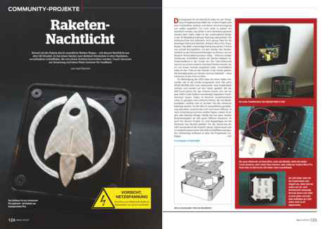 The rocket nightlight was presented in the German MAKE magazine 06/2016 as a community project. Thank you! 🙂
The link or a click on the picture take you to the table of contents of issue 06/2016. If you have questions concerning this project do not hesitate to contact me! <foobar@zeropage.io>
Project Description
You can find a great design for a LED nightlight with various emblems or logos like Stormtrooper, Superman, Punisher, etc. on Thingiverse. This design is based on a 3D printed case with a transparent and extruded inlay of the emblem/logo in the lid. The case has a hole on the backside to have an external power supply feed the internal light source, e.g., an RGB light stripe or similar.
I reworked this design to create a nightlight that
- does not need an external power supply, i.e., has a plug and can be directly plugged into a wall socket
- has touch switches to easily adjust the brightness, light effects (or modes), colors etc.
- uses a piezo buzzer to acknowledge touch switch triggers and to play the first notes from the Imperial March when plugged into a socket (a little annoying, but can be switched off;-)
- utilizes a mounting platform for six RGB LEDs that can be easily inserted into the case
- fixes some minor issues in the original design (displaced inlay and mounting hole)
- comes with a variety of light effects like fixed colors, strobe, or cyclone chase
Payload
1 x Arduino Pro Mini 5V 16MHz // Merchants on eBay offer a plethora of pro minis. Take care when ordering: The pro mini is available as 3,3V and 5V as well as 8MHz and 16MHz versions. Moreover: Many vendors are located in China; shipping may take a long time to your home country.
1 x Piezo buzzer // One of these (eBay) should work.
1 x Power supply // I used this EMSA050120, 5 V-/1,2 A from Pollin to harvest the mains supply circuit and the plug.
4 x 3D printed part // These parts comprise a case, an LED holder, a plate (or lid) and an emblem/logo. You will find the 3D templates as STL files on Thingiverse.
6 x RGB LED // The WS2812b have a nice color range and are usually cheapest when bought as an LED stripe. I had some spare LEDs from another project. You can order them on eBay or here (1m stripe, Roboter Bausatz Shop).
4 x M5, 16mm counter-sunk screw
1 x Software // The software for the Arduino is available in my Nightlight Late-Night Edition repository on GitHub.
Moreover a Dremel or similar to cut open the mains adapter, pliers, rasps, wires, some metal splints for the touch sensors, and, of course, a soldering iron.
Nightlight 3D Parts
The nightlight consists of four 3D printed parts; cf. the sandwich picture showing the different layers.
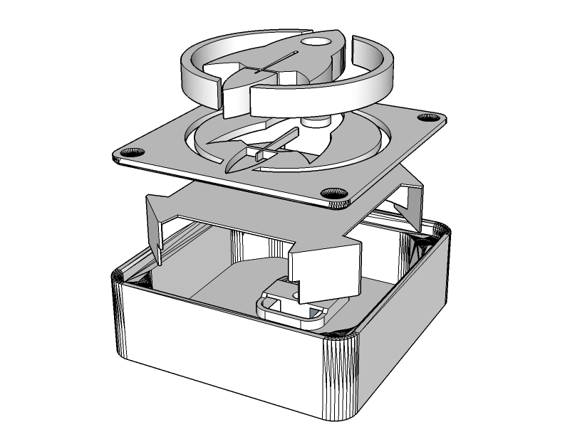
From bottom to top: 1) Case to host the mains supply circuit, Arduino pro mini, piezo buzzer, LEDs, touch switches, cables, and the plug. 2) LED holder. 3) The top plate and 4) the extruded emblem inlay.
3D Part 1: The Case
The case from the original design was only 13mm high (inner height) and, thus, not tall enough to host the electronic parts. I had to import the STL file into SketchUp and stretch the case on the z-axis to an inner height of 25mm. That gave me just enough space to squeeze the LED holder above the mains supply circuit into the case and still have 2 or 3mm distance from the top plate. The more space you have between the LEDs and the plate, the better the light will be diffused. But I did not want the nightlight to be more bulky than necessary so 25mm inner height had to suffice.
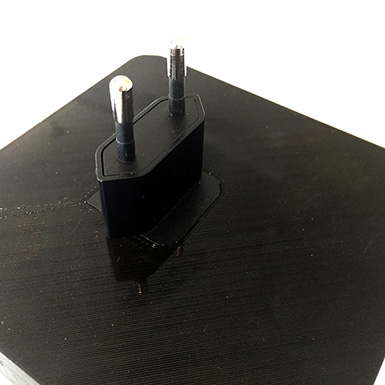
Increasing the height was the easy part. Designing the plug holder on the backside of the case was more difficult. I first measured the dimensions of the plug as precise as possible, then started to design a plug holder with SketchUp.

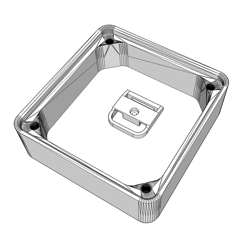
It took a couple of iterations and an according number of test prints until, finally, the plug snapped into the plug holder with a satisfying “click”. The plug fits so tight that I consider it to be unremovable without destroying the case. And I may add that this is by design since we are dealing with 230V AC power and the nightlight must be impenetrable by adventurous kid’s hands.
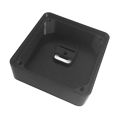
The case was printed with black REC PLA at 210°, bed temperature 60°, no support, 0.16mm height, 1.2mm wall thickness, and 66% infill. It depends on your 3D printer’s bridging abilities if the plug holder will be ok without support. If unsure, print the case with support turned on.
3D Part 2: The LED Holder
I wanted the LEDs in the nightlight to be on a planar surface to get an even illumination. The idea was to construct an LED holder in SketchUp that tightly fits into the case without gluing, is rather stable, and has legs to stand on. The images show what I came up with.
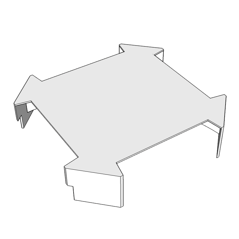


Luckily, the LED holder nearly immediately matched all of the above mentioned criteria. I chose white innofil3D PLA for the print since a white background looked best behind the semi-transparent inlay.
3D Part 3: The top Plate
The plate was printed with black REC PLA and the same print parameters as for the case (210°, bed temperature 60°, no support, 0.16mm height, 1.2mm wall thickness) except that infill was set to 100%. I did not want any light to escape through the plate. With a proper number of top and bottom layers 100% infill with black PLA might be an extreme overkill but I played it safe.


With 100% infill the plate came out rock solid which has another advantage: Some parts might need to be sanded so that the extruded emblem/logo wil fit into the plate. The more solid your parts, the better they can be sanded.
3D Part 4: The Emblem/Logo
The extruded rocket inlay was printed with transparent innofil3D PLA. You will notice that “transparent” is in no way comparable to acrylic glass or alike. Moreover, parts printed with this PLA look yellowed; like they have been exposed for too long in the sun. Nonetheless, this kind of transparency is the best you can get with current fused deposition modelling (FDM) based desktop 3D printers and PLA. Nylon and other filament materials might yield better results but they are more difficult to print and handle.
Infill was set to 22%. You will see the honeycomb pattern, or whatever type of infill you chose in your slicer, with such a low infill value. But more infill also means losing transparency. I was fine with 22%.
Avengers assemble!
Let’s put the hardware together.
Complete the Plate
 The transparent emblem/logo has to be merged with the plate. Depending on the design there might be a couple of “loose” parts from the plate print that need to be inserted into the emblem/logo first. Rasps and sanding paper are your best friend in this step since the parts will most likely not fit straight off the 3D printer. While 3D prints are usually pretty nice, there are limits to the precision you can expect from FDM prints. The rocket has only one loose part which is the round window. That one is pretty easy to insert. If not, rasp and apply mild force. Do not apply too much pressure to the small parts – they might break or damage the plate. If in doubt, sand more and re-try often. It will finally fit. If all loose parts are pushed in the emblem/logo you will want to merge the emblem/logo with the plate. That might need some sanding too. The small and tall middle wing of the rocket will most likely need some sanding. Be very careful since it can break off easily. Carefully push the transparent part into the plate. A vise or a hammer might come in handy, depending on how brave you are. This step requires patience.
Disassemble the Power Supply
As mentioned in the Payload-section I used a very cheap EMSA050120 power supply from Pollin to harvest the mains supply circuit and the plug. The case turned out to be very intractable and successfully resisted my attempts to pry it open it with a screw driver or pliers. I could have tried to pop it open in the vise but did not want to risk damaging the PCB/electronics inside. Well, let’s mill it open – Dremel time!


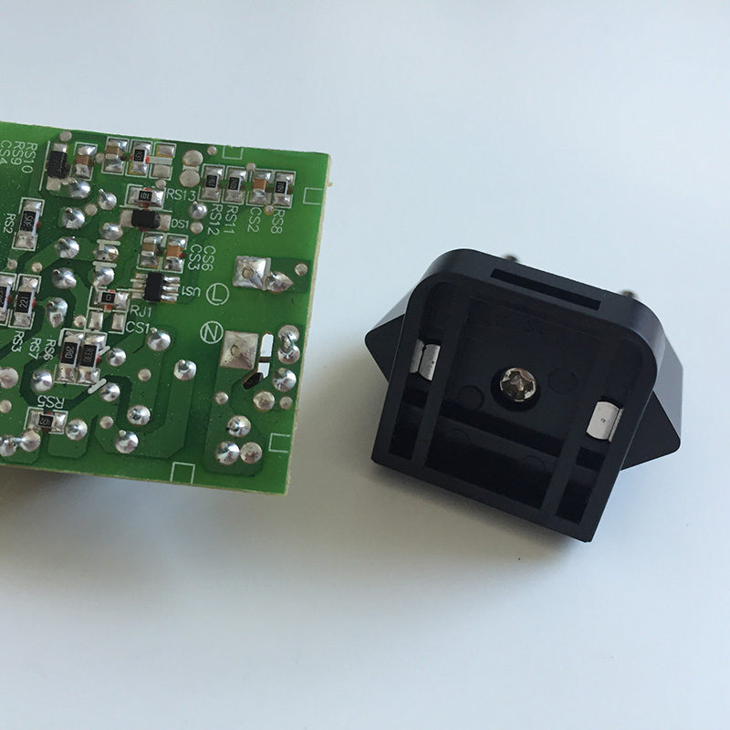
Caveat: Always mill with safety glasses and use protective gloves. The picture is just for demonstration purposes. Milling plastic produces foul-smelling, and most likely toxic, fumes. Do it outdoors. The picture in the middle shows the mains supply circuit along with the plug. In the next picture you can see the backside of the supply circuit with the big L- and N-conductance pads on the right-hand side of the PCB.
Solder Wires on Plug
The plug will be connected with solid copper cables to the L- and N-conductance pads of the mains supply circuit.
Before we can solder the cables two small plastic bars have to be removed from the plug. I use pliers to simply break them off. After that I start to solder the cables on the plug’s connection pads (to the left and right of the middle screw). Or I tried because this turns out to be an epic soldering fail. I try a dozen times but can’t get the, sorry, GODDAMMIT cables to solder-join with the pads. The pads literally refuse to be soldered! But resistance is futile and a couple of search engine queries later I seem to be wiser: The pads are made of stainless steel which is pretty hard to solder with normal tin-solder. If not impossible at all. What I need is soldering fluid, something like this (Conrad).


If you read the soldering fluid’s hazard notes, well, you do not really want to use this stuff: Serious chemical burns of skin and eyes, irritating to the respiratory system, and so on and so forth. Zinc chloride is no fun. Keep away from children! After some more failed attempts even with the soldering fluid I learned that the pads need much more heat to join forces with the cables than I was used from soldering usual electronics stuff. So, finally, I got two nice solder joints. FTW!
Drill Holes for Touch Sensors
 It is always a good idea to think before you act. And I wish I’d done that before printing the case since I forgot to add two 4mm holes for the touch sensors on the right-hand side of the case! Facepalm! Printing the case again just because two holes were missing was not an option. But we are not only apt with additive but also with subtractive manufacturing: I drill the holes with a 3mm wood drill and get a perfect diameter after some minor rasping. PLA is fairly easy to drill, e.g. compared to acrylic glass. But you may have to lift the drill from time to time to remove excess plastic. Wood drills are designed to automatically forward the excess wood to the top of the drill and out of the drill hole. When you drill PLA or other plastic materials it tends to melt and get stuck on the drill. The slower you drill, the better. Applying some drops of water or sewing-machine oil is said to help (not tried so far).
Connect Mains Supply Circuit to Plug
In this step we connect the mains supply circuit to the plug and fix the circuit in the case.
First pop the plug into the case’s plug holder. Since the copper wires are pretty rigid it is a good idea to shorten and bend them properly before soldering the wires to the mains supply circuit.
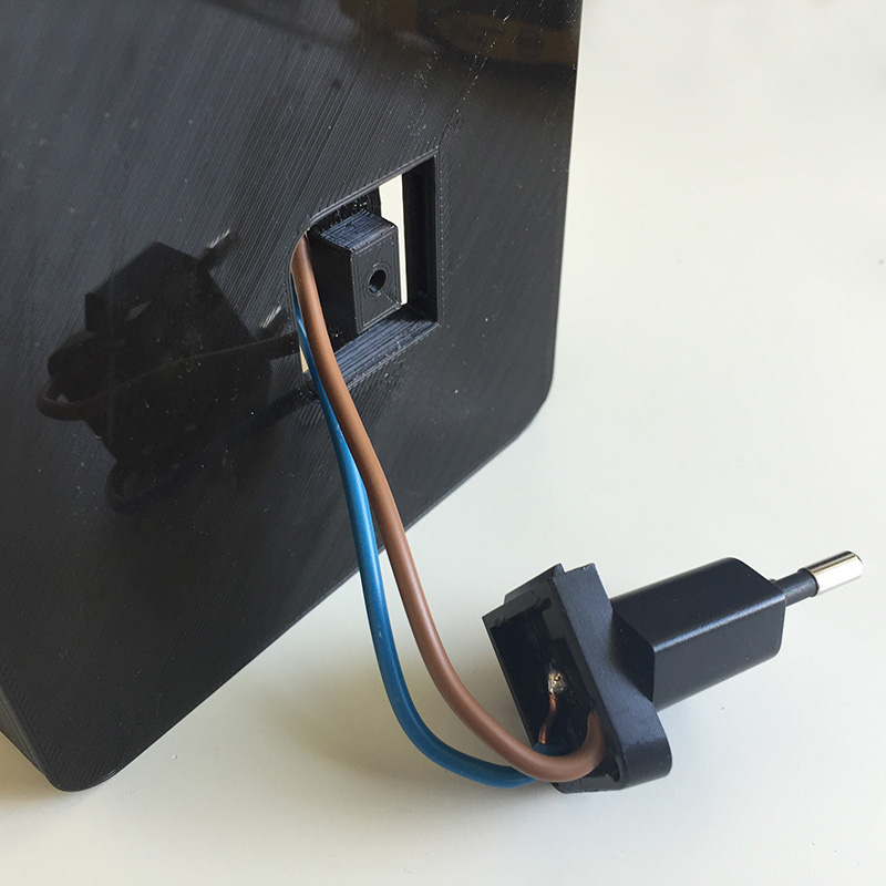


Solder the mains supply circuit’s L-conductance pad to the brown copper wire. Repeat with the N-conductance pad and the blue wire. Finally, attach the mains supply circuit to the bottom of the case. You can see the black and red 5V power supply cables on the left-hand side of the mains supply circuit. We will use these later to power the LEDs and the Arduino microcontroller.
Attach LEDs to LED Holder
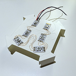 I decided to use six WS2812b LEDs and arranged them on the holder in a pattern that showed the most even illumination level during my tests. In case you’re a Lumen junkie there is enough room to cramp more LEDs on the holder. The LED strips usually come with sticky tape on their backside so gluing them on the holder is easy. After that I used 0.15mm enamelled copper wire to solder the connections between the +5V, GND and D
Prepare the Touch Sensors
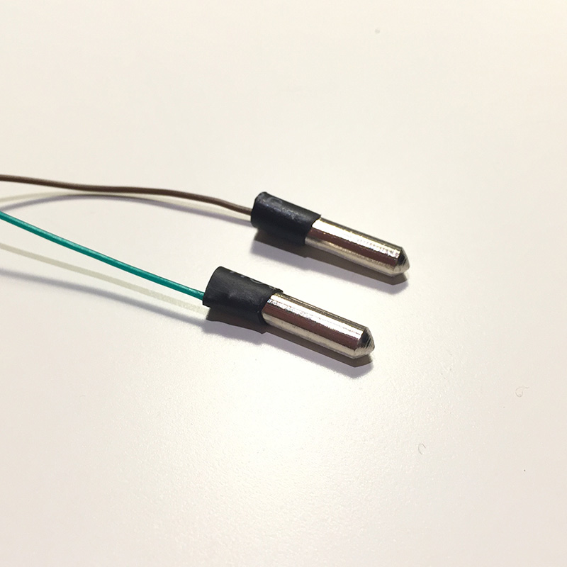 This nightlight requires two touch sensors to control its various functions. The Arduino library ADCTouch makes it very easy to add touch sensors to a project. You can connect nearly everything that changes its capacity when touched to an arbitrary analogue pin of the microcontroller and have that thing act like a touch sensor. In this project I use two small metal splints that will be stuck and glued in the drilled holes on the right-hand side of the case. To connect the splints to the Arduino I have to solder wires to them. Since they are made of stainless steel, I have to use soldering fluid again. One drop on each splint, plenty of heat, a little tin solder, and some heat shrink tubing later the two touch sensors are ready.
Wire it up!
The Fritzing breadboard view shows how the electronic components are wired up to the Arduino pro mini.
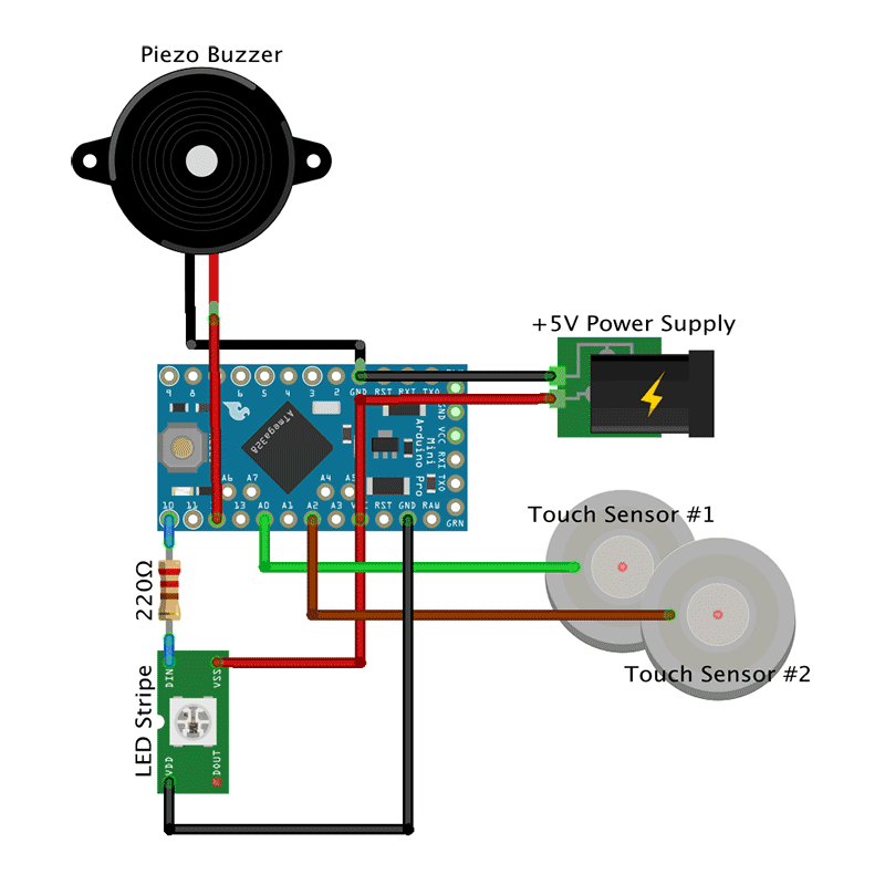
You can choose different pins on the Arduino by adjusting the Arduino Sketch accordingly.
- +5V from the power mains supply circuit goes to the VCC pin while ground is connected to the GND pin on the Arduino.
- The piezo buzzer’s negative pole is connected to the GND pin, the positive pole to pin 12.
- The upper touch sensor goes to pin A0.
- The lower touch sensor goes to pin A2.
- The view shows symbolically only one LED, not the wiring of all six LEDs. The first LED’s Din is connected via a 220 Ohm resistor to pin 10. It is usually advised to use a resistor to cover power spikes that could harm the LEDs. VSS or +5V on the LED is connected to the VCC pin on the Arduino. VDD or ground on the LED is wired to the a GND pin.
That’s how it looks like when all components have been soldered and put into place in the case.


I used hot glue to paste the Arduino and the piezo buzzer on the case. The touch sensors were easier to attach with super glue.
Light and Diffusion
We need to diffuse the light that is emitted by the LEDs so that the transparent rocket is evenly illuminated. I already had some experience with diffusion materials from another project where I tried normal paper with different grammages, frosted acrylic glass, and Ripstop. The results were ok, but not perfect. I followed a hint that white baking paper yields good diffusion results. Unfortunately, I was not able to find white baking paper; only the usual brown one. Next I tried sandwich paper (sic!) and that’s what I found to work best when it comes to LED light diffusion. Of course, it depends on what you are building and especially, how much space there is between the LEDs and the material of the boundary layer. Try different materials and find the one that best suits your needs. However, I like the sandwich paper and, thus, taped a double layer on the backside of the plate. After that, the plate is screwed to the case with four black M5x16mm counter-sunk screws. I wanted screws with no imprint on the screw head but did not pay (enough) attention to the seller’s pictures on eBay. So, always take a very close look at what you intend to buy. 😉 NB: The screws have to cut their way through the holes in the case so it can get tedious to get them in. Use appropriate force. Moreover, the screw heads were bigger than expected so I had to widen the reception holes on the lid’s front side with a hand countersink.
Code is Poetry
All that hardware does not do anything without the proper software. We need a sketch (aka program) for the Arduino pro mini so the nightlight will do the things described in the project description. Two of the used libraries are worth mentioning: The awesome FastLED library to control the RGB LEDs. And the ADCTouch library to easily turn a cable or a splint into a touch sensor. The sketch makes use of the Arduino’s inbuild non-volatile EEPROM to store modes, colors, and other stuff that can be reloaded the next time the nighlight is powered up. The most complicated part of the code is handling the touch sensors. Both sensors react to short (1st function), middle-long (2nd function) and long touches (3rd function) and trigger different functions depending on the touch durations. Sounds complicated, but is not. Or is it?
Upper sensor
- Short touch. Increase brightness of LEDs until maximum is reached (17 steps). Then turn LEDs off.
- Middle-long touch. Immediately return brightness to lowest setting, i.e., one step above zero.
- Long touch. Toggle playing Imperial March on power-up on/off.
Lower sensor
- Short touch. Change color, speed, or whatever of current lighting mode.
- Middle-long touch. Switch to next light mode.
- Long touch. Immediately switch to first light mode, i.e., fixed color.
You can find the code in my Nightlight Late-Night Edition repository on GitHub.
Ready Player One
That was a real fun project and the roket nightlight turned out to be a full success!
Sep 2016, i.f.

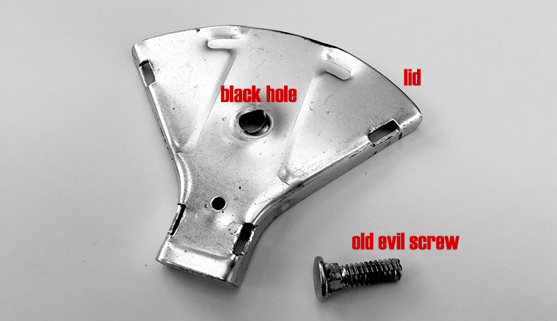
Lord Overhaul: How to fix a rake’s missing wing nut
Our rake lost its wing nut that is used to fix the pusher for the blades.

On first inspection I thought, that I just take any other M5 wing nut and that thing is good for another ten years of gardening service. But far wrong. The ISO metric screw threads (Wikipedia) come in different pitches: fine, middle, and coarse (at least in Germany). The thread in the rake must be either middle or coarse. At least none of my fine nuts fits on the thread.
So what now? Make or buy? Buy a couple of wing nuts? Buy a new rake? Of course not. Let’s replace the screw with a M5 fine pitched one.

First step: Pry open the lid. Done. Second step: Remove the old screw. Not an easy task since the manufacturer first drilled a hole and then pushed or hammered the screw through the hole so it stuck really, really tight. After a couple of miserable attempts to remove it with pliers I realized that there is only one appropriate tool for this job: A hammer. The evil screw is out.
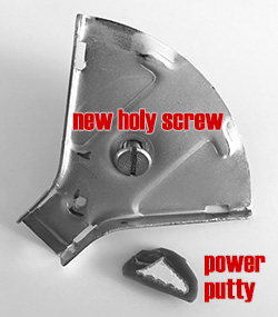
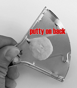
Let’s see how we get the new screw attached to the lid. Soldering stainless steel is difficult. Welding would surely work but is somewhat impossible without weldering equipment. Last resort: Glue! Hot glue, not durable enough. The same might apply to super glue. But two-component power putty should be fine.

Funny thing: I do have nuts, but no wing nuts! Duh! So let’s print a wing nut using the awesome Ultimate Nut Knob Generator (Thingiverse) by wstein. Here it is.
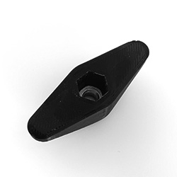
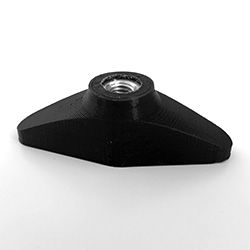
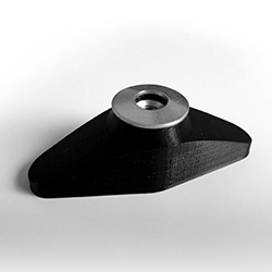
I super glued a washer on the outer side so the PLA will not be squashed or damaged when the wing nut is tightened. Now it’s time to put the pieces back together.
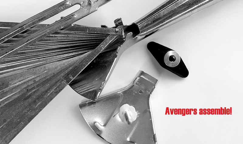
Avengers assemble!
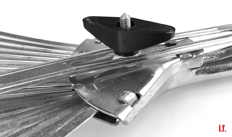
All set and done. Let the gardening begin!
Ultimaker 2+ Low Friction Spool Holder with Bearings
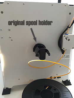 The spool holder shipped with the Ultimaker2+ is ok and with the new extruder there should be no issues with underextrusion. Depending on the size and type of the filament spool you might encounter squeaking noises from time to time. Surely not serious enough an issue to substitute the spool holder. But what if a spool does not fit on the spool holder and gets completely jammed? That’s what exactly happened with a spool from REC. Time for a new spool holder!
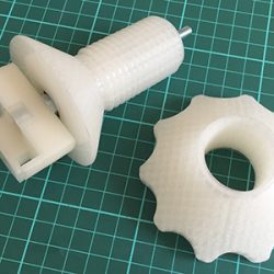
sneakypoo designed a nice bearing based Low friction spool holder and put it on Thingiverse. Thank you! The spool holder requires five 3D printed parts together with two bearings, a threaded rod and a couple of nuts. It comes in two different lengths for big and not so big spools as well as two different diameters to either fit 626 or 608 bearings.
I printed the short 608 version which is sufficient for standard 750g filament spools. The holder is very well designed and everything fit perfectly. Except the spacer which was too long so I had to rasp it down by approximately 4-5mm. A couple of commenters already pointed that out on Thingiverse. So trust them (or me, or all of us) and shrink the spacer in your slicer prior to printing!
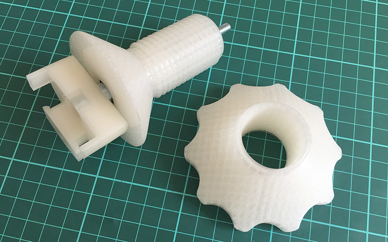
The following picture shows the order in which the parts have to be assembled.

The assembled spool holder.
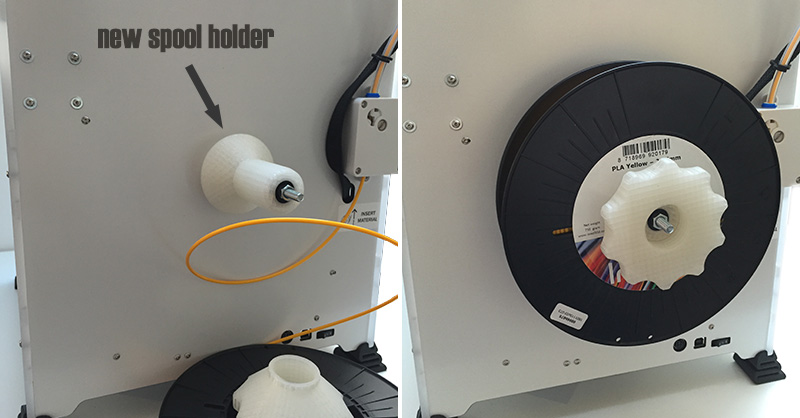
And the new spool holder attached to the Ultimaker.
Check sneakypoo’s video to see what low friction looks like in real life. Awesome!
That thing is virtually noiseless and gives real Jesus gliding action. Luv it!
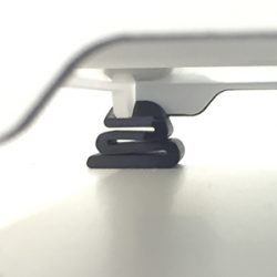
Noise dampening feet for Ultimaker2
3D printers can be quite noisy. Besides a full encapsulation that might also proof valuable if printing ABS there are other ways to lower the volume. One is to reduce the vibration that is transferred from the moving parts of the printer to its case and from there to the table which resonates and, depending on size and material, is likely to subsequently work like a noise amplifier.
This effect can be reduced with noise dampening feet. There are a already lot of dampening feet designs available on Thingiverse or YouMagine so there is no need to design a new one. The Damping foot UM original by Kees de Ligt looks promising.
 The first foot printed well with black REC filament using 0.15mm layer height, 0.8mm shell thickness, 35% infill, support, and with the square side facing the print bed. I use “hotter than normal” settings for the REC PLA: 215° noozle and 70° bed temperature. These temperatures provide nice prints and good platform adhesion with the REC filament. After that I got lightheaded and tried to print the remaining three feet all at the same time. While this is usually not a big deal, the REC PLA filament consistently turns out to be somewhat picky. Too much cooling time between the layers and the prints tend to fail.
This is how the three-at-the-same-time fail looks like.
 Heavily warped edges on the bottom-most print. The first layers of the dampening foot in the middle look ok. But the top-most foot has been utterly destroyed. You’re on the lucky side if you notice such failures early enough to abort the print and, thus, avoid wasting material.
As I took a closer look at the dampening foot that was printed first, I realized that I would need two of the feet “as is” and another two feet mirrored at the y-axis. Only this way all four feet would face the same direction when attached to the printer. So, I should be thankful that the simultaneous print of three feet failed since that would have produced two unmirrored feet. You can easily mirror objects at all axes in Cura: Click the object then hit the mirror button on the bottom left and click on of the Mirror X/Y/Z buttons.
The remaining one foot as well as the y-mirrored two feet print like a charm. Attaching the feet is easy: Lift one corner of the printer and push the corresponding foot underneath this corner. Repeat with all other corners. Done.
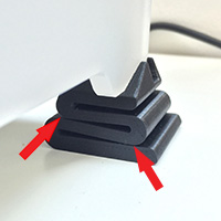 [Update] There is definitely a damping effect resulting in a less noisy soundscape. Good! But after a couple of prints the two rear feet have been tightly compressed so the curvatures of the snake-like construct touch each other. Hence, the damping characteristics of the rear feet are lost. Reason: The 35% infill and 0.8mm outer shell thickness are to weak to support the heavy rear part of the Ultimaker. Solution: Using 1.2mm outer shell thickness and 90% infill yields a new “as is” rear-left foot, and a new y-mirrored rear-right foot that are of heavy duty quality and now easily support the Ultimaker’s rear side.
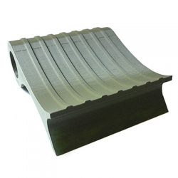
3D Model: Heavy Duty Ice Scraper
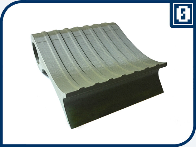
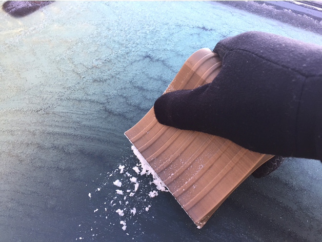


A word on usability: I believe that most commercially available ice scrapers have a faulty design especially with respect to the handle. The longer the handle gets, the more difficult it is to apply proper force on the scraper part. And due to cheap production the scraping area usually isn’t flat but wobbly.
mishmish4 designed a nice, short and sturdy Ice Scraper that you can find here on Thingiverse. The twist-in-place handle is a nice design detail, but, to my mind, it does not add to usability.
I used this design as the basis for my Heavy Duty Ice Scraper. Unfortunately, mishmish4’s STL was not editable for me in SketchUp so I redesigned that thing anew omitting the handle and choosing a somewhat sleeker design.
Please note that there are two versions available:
Heavy Duty Ice Scraper FINAL.stl— This one has a 4cm diameter grip bar. You should have fairly big hands to achieve a decent scraping job with this.Heavy Duty Ice Scraper FINAL (oval).stl— This one has a ~3.5cm diameter at the widest side of the grip bar. I squeezed the scraper along the vertical axis so the grip bar is now oval instead of round. I think that this one is better to handle but, again, it depends on the size of your hands.
Print Settings
Nozzle: 0.4mm
Walls: 3
Resolution: 0.16mm
Infill: 66%
Rafts: No
Supports: No
Notes
Definitely print the scraper _on its side_. This way you will not need support and the printing time is reduced. The combination of 66% infill with a shell thickness of 1.2mm yielded a pretty sturdy scraper.
3D printed resistor storage box with wall mount
Quite some time ago I ordered five E12 series resistors that I received in a plethora of plastic bags. One plastic bag for every resistor value. And since there are 12 resistors in each series, I had 60 plastic bags with resistors ranging from 10 Ohm to 820 kOhm lying around. That is the antitheses of orderliness and usability.
Browsing Thingiverse I came across this nice little resistor storage box.
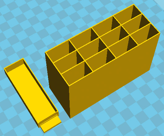
Each box has 12 drawers to hold all resistors from one E12 series. Printing five (actually six with a test print) boxes and 60(!) drawers was a lengthy process.
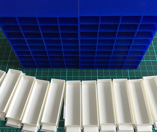
The result is ok. Though deliberately choosing a low print quality for the drawers (=less printing time) combined with warped backsides of the boxes required some reworking with a cutter blade and sanding paper. I use super glue to stack the boxes on top of each other and put the resistors into their drawers.
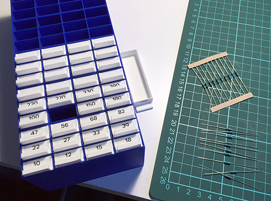
The drawers have a 17x6mm cavity at the front that can be used as a label field. Labeling the drawers is mandatory since there is not much sense in putting resistors into drawers without knowing which resistor has which resistance… 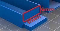 Unless, of course, you like to compare the color rings with a resistor color table. It would be an interesting idea to build a simple Arduino-based auto-ranging ohmmeter and attach it to the top or bottom of the storage box phalanx; note to self for a later project. A label writer with 6mm tapes helps in creating and easily attaching the labels. Another solution would be to print, cut, and glue the labels. Hand writing might be an option, or you could even 3D print the labels which would be yet another fine Sisyphean task.
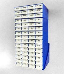
Now that the drawers have been labeled and all resistors are stored in their according drawer we have to think about where to place the resistors. When simply put on a table it will be hard to read the resistances of the drawers at the bottom of the stack of boxes. Moreover, the drawers can easily be pushed and pulled which is good for accessing the resistors but bad if the stack of boxes is jerked and the drawers start to slide out by themselves. Or, even worse, the box gets knocked over and spills all resistors on the table and floor. In order to properly read the labels I would like to attach the stack of boxes to the wall at eye level. And I want the boxes to be slightly tilted upwards so the drawers will not slide out by themselves.
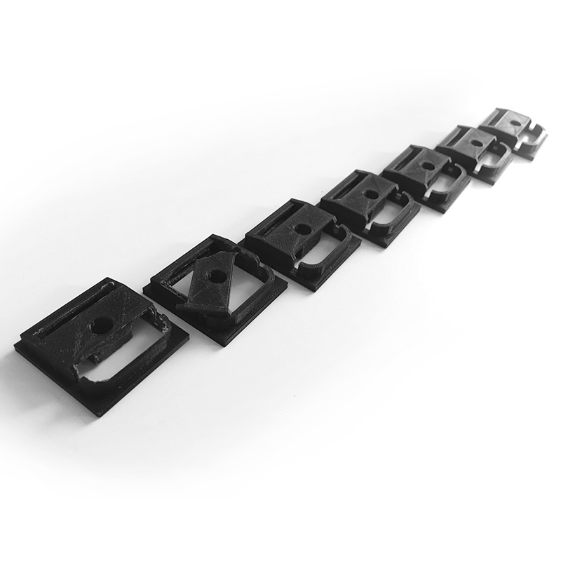
Let’s create a wall mount with SketchUp!
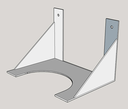
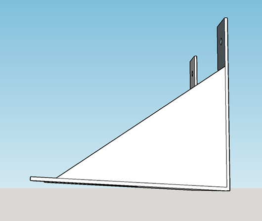
You can download the STL file here. The next picture shows the box holder screwed to the wall. The holder looks distorted but this is due to the chosen perspective for the photography.
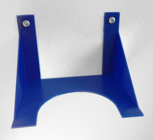
Finally, the stack of resistor boxes is super glued to the holder. Major achievement: “order and stability in our [resistor] country.”

“Resistance is futile!”
i.f.