 This project powers electronic components (5V) with a mains supply circuit (230V > 5V) that is connected to a power plug (230V). If you are going to build this, make sure that you know what you do. In case of doubt, consult a skilled person that is familiar with mains voltage or use a safe power source like a line adapter or batteries.
tl;dr A nightlight based on a reworked Thingiverse design with Arduino-controlled LED light effects, touch sensors, and a piezo buzzer humming the first notes from the Imperial march. Watch the video to see it in action. Detailed instructions start below video.
Bragging rights
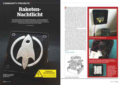 The rocket nightlight was presented in the German MAKE magazine 06/2016 as a community project. Thank you! 🙂
The link or a click on the picture take you to the table of contents of issue 06/2016. If you have questions concerning this project do not hesitate to contact me! <foobar@zeropage.io>
Project Description
You can find a great design for a LED nightlight with various emblems or logos like Stormtrooper, Superman, Punisher, etc. on Thingiverse. This design is based on a 3D printed case with a transparent and extruded inlay of the emblem/logo in the lid. The case has a hole on the backside to have an external power supply feed the internal light source, e.g., an RGB light stripe or similar.
I reworked this design to create a nightlight that
- does not need an external power supply, i.e., has a plug and can be directly plugged into a wall socket
- has touch switches to easily adjust the brightness, light effects (or modes), colors etc.
- uses a piezo buzzer to acknowledge touch switch triggers and to play the first notes from the Imperial March when plugged into a socket (a little annoying, but can be switched off;-)
- utilizes a mounting platform for six RGB LEDs that can be easily inserted into the case
- fixes some minor issues in the original design (displaced inlay and mounting hole)
- comes with a variety of light effects like fixed colors, strobe, or cyclone chase
Payload
1 x Arduino Pro Mini 5V 16MHz // Merchants on eBay offer a plethora of pro minis. Take care when ordering: The pro mini is available as 3,3V and 5V as well as 8MHz and 16MHz versions. Moreover: Many vendors are located in China; shipping may take a long time to your home country.
1 x Piezo buzzer // One of these (eBay) should work.
1 x Power supply // I used this EMSA050120, 5 V-/1,2 A from Pollin to harvest the mains supply circuit and the plug.
4 x 3D printed part // These parts comprise a case, an LED holder, a plate (or lid) and an emblem/logo. You will find the 3D templates as STL files on Thingiverse.
6 x RGB LED // The WS2812b have a nice color range and are usually cheapest when bought as an LED stripe. I had some spare LEDs from another project. You can order them on eBay or here (1m stripe, Roboter Bausatz Shop).
4 x M5, 16mm counter-sunk screw
1 x Software // The software for the Arduino is available in my Nightlight Late-Night Edition repository on GitHub.
Moreover a Dremel or similar to cut open the mains adapter, pliers, rasps, wires, some metal splints for the touch sensors, and, of course, a soldering iron.
Nightlight 3D Parts
The nightlight consists of four 3D printed parts; cf. the sandwich picture showing the different layers.
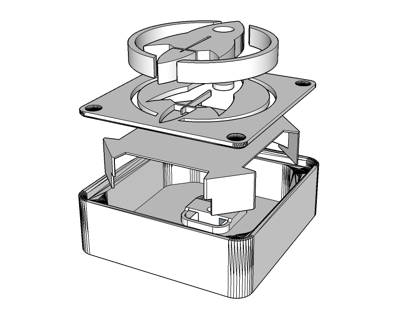
From bottom to top: 1) Case to host the mains supply circuit, Arduino pro mini, piezo buzzer, LEDs, touch switches, cables, and the plug. 2) LED holder. 3) The top plate and 4) the extruded emblem inlay.
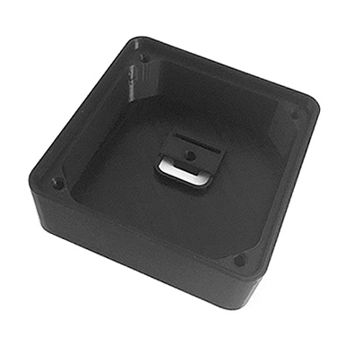
3D Part 1: The Case
The case from the original design was only 13mm high (inner height) and, thus, not tall enough to host the electronic parts. I had to import the STL file into SketchUp and stretch the case on the z-axis to an inner height of 25mm. That gave me just enough space to squeeze the LED holder above the mains supply circuit into the case and still have 2 or 3mm distance from the top plate. The more space you have between the LEDs and the plate, the better the light will be diffused. But I did not want the nightlight to be more bulky than necessary so 25mm inner height had to suffice.
Increasing the height was the easy part. Designing the plug holder on the backside of the case was more difficult. I first measured the dimensions of the plug as precise as possible, then started to design a plug holder with SketchUp.

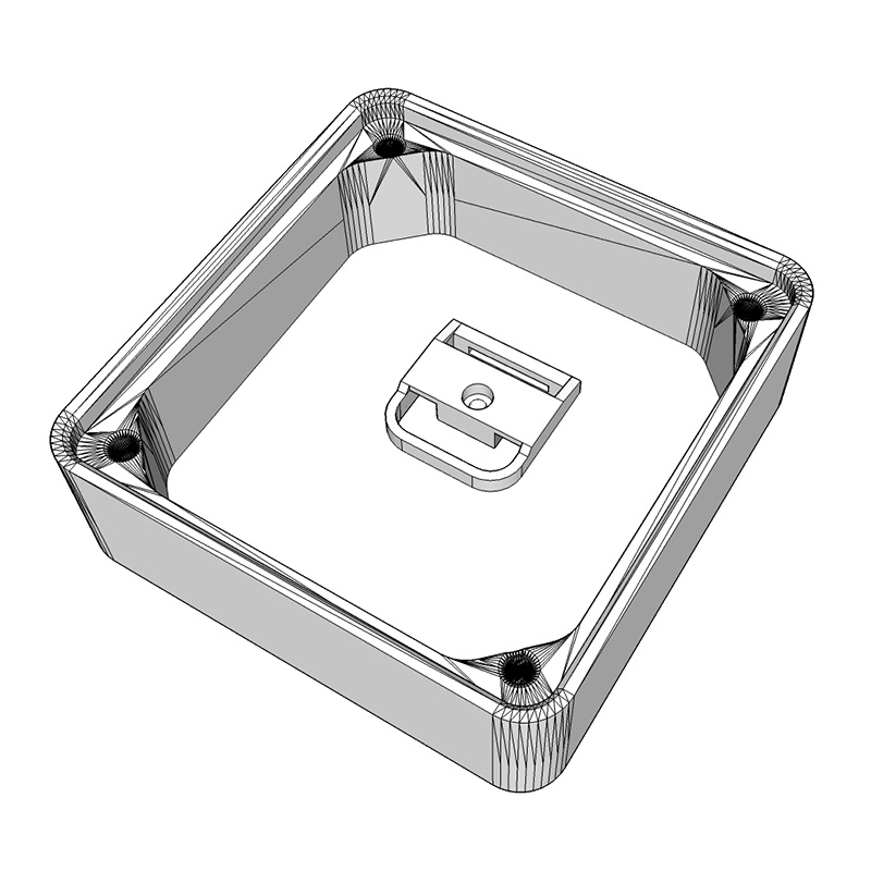
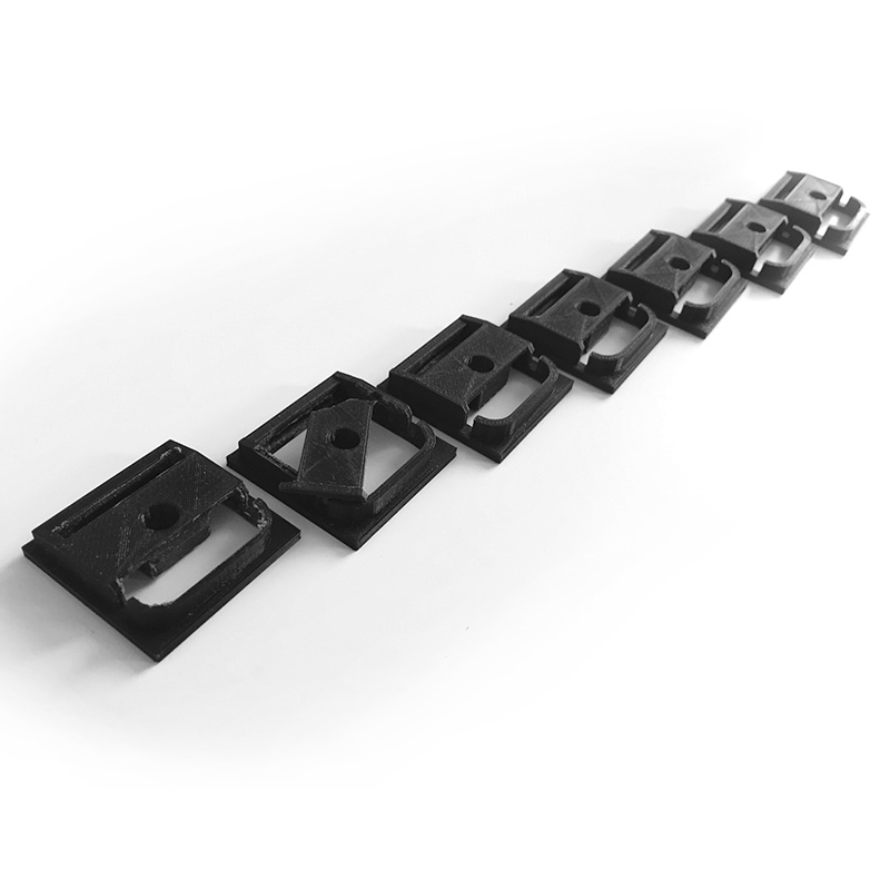
It took a couple of iterations and an according number of test prints until, finally, the plug snapped into the plug holder with a satisfying “click”. The plug fits so tight that I consider it to be unremovable without destroying the case. And I may add that this is by design since we are dealing with 230V AC power and the nightlight must be impenetrable by adventurous kid’s hands.
The case was printed with black REC PLA at 210°, bed temperature 60°, no support, 0.16mm height, 1.2mm wall thickness, and 66% infill. It depends on your 3D printer’s bridging abilities if the plug holder will be ok without support. If unsure, print the case with support turned on.
3D Part 2: The LED Holder
I wanted the LEDs in the nightlight to be on a planar surface to get an even illumination. The idea was to construct an LED holder in SketchUp that tightly fits into the case without gluing, is rather stable, and has legs to stand on. The images show what I came up with.
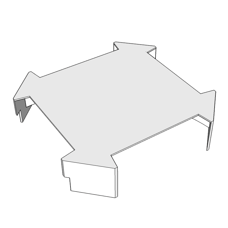


Luckily, the LED holder nearly immediately matched all of the above mentioned criteria. I chose white innofil3D PLA for the print since a white background looked best behind the semi-transparent inlay.
3D Part 3: The top Plate
The plate was printed with black REC PLA and the same print parameters as for the case (210°, bed temperature 60°, no support, 0.16mm height, 1.2mm wall thickness) except that infill was set to 100%. I did not want any light to escape through the plate. With a proper number of top and bottom layers 100% infill with black PLA might be an extreme overkill but I played it safe.


With 100% infill the plate came out rock solid which has another advantage: Some parts might need to be sanded so that the extruded emblem/logo wil fit into the plate. The more solid your parts, the better they can be sanded.
3D Part 4: The Emblem/Logo
The extruded rocket inlay was printed with transparent innofil3D PLA. You will notice that “transparent” is in no way comparable to acrylic glass or alike. Moreover, parts printed with this PLA look yellowed; like they have been exposed for too long in the sun. Nonetheless, this kind of transparency is the best you can get with current fused deposition modelling (FDM) based desktop 3D printers and PLA. Nylon and other filament materials might yield better results but they are more difficult to print and handle.
Infill was set to 22%. You will see the honeycomb pattern, or whatever type of infill you chose in your slicer, with such a low infill value. But more infill also means losing transparency. I was fine with 22%.
Avengers assemble!
Let’s put the hardware together.
Complete the Plate
 The transparent emblem/logo has to be merged with the plate. Depending on the design there might be a couple of “loose” parts from the plate print that need to be inserted into the emblem/logo first. Rasps and sanding paper are your best friend in this step since the parts will most likely not fit straight off the 3D printer. While 3D prints are usually pretty nice, there are limits to the precision you can expect from FDM prints. The rocket has only one loose part which is the round window. That one is pretty easy to insert. If not, rasp and apply mild force. Do not apply too much pressure to the small parts – they might break or damage the plate. If in doubt, sand more and re-try often. It will finally fit. If all loose parts are pushed in the emblem/logo you will want to merge the emblem/logo with the plate. That might need some sanding too. The small and tall middle wing of the rocket will most likely need some sanding. Be very careful since it can break off easily. Carefully push the transparent part into the plate. A vise or a hammer might come in handy, depending on how brave you are. This step requires patience.
Disassemble the Power Supply
As mentioned in the Payload-section I used a very cheap EMSA050120 power supply from Pollin to harvest the mains supply circuit and the plug. The case turned out to be very intractable and successfully resisted my attempts to pry it open it with a screw driver or pliers. I could have tried to pop it open in the vise but did not want to risk damaging the PCB/electronics inside. Well, let’s mill it open – Dremel time!


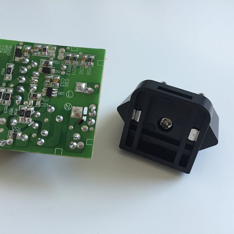
Caveat: Always mill with safety glasses and use protective gloves. The picture is just for demonstration purposes. Milling plastic produces foul-smelling, and most likely toxic, fumes. Do it outdoors. The picture in the middle shows the mains supply circuit along with the plug. In the next picture you can see the backside of the supply circuit with the big L- and N-conductance pads on the right-hand side of the PCB.
Solder Wires on Plug
The plug will be connected with solid copper cables to the L- and N-conductance pads of the mains supply circuit.
Before we can solder the cables two small plastic bars have to be removed from the plug. I use pliers to simply break them off. After that I start to solder the cables on the plug’s connection pads (to the left and right of the middle screw). Or I tried because this turns out to be an epic soldering fail. I try a dozen times but can’t get the, sorry, GODDAMMIT cables to solder-join with the pads. The pads literally refuse to be soldered! But resistance is futile and a couple of search engine queries later I seem to be wiser: The pads are made of stainless steel which is pretty hard to solder with normal tin-solder. If not impossible at all. What I need is soldering fluid, something like this (Conrad).


If you read the soldering fluid’s hazard notes, well, you do not really want to use this stuff: Serious chemical burns of skin and eyes, irritating to the respiratory system, and so on and so forth. Zinc chloride is no fun. Keep away from children! After some more failed attempts even with the soldering fluid I learned that the pads need much more heat to join forces with the cables than I was used from soldering usual electronics stuff. So, finally, I got two nice solder joints. FTW!
Drill Holes for Touch Sensors
 It is always a good idea to think before you act. And I wish I’d done that before printing the case since I forgot to add two 4mm holes for the touch sensors on the right-hand side of the case! Facepalm! Printing the case again just because two holes were missing was not an option. But we are not only apt with additive but also with subtractive manufacturing: I drill the holes with a 3mm wood drill and get a perfect diameter after some minor rasping. PLA is fairly easy to drill, e.g. compared to acrylic glass. But you may have to lift the drill from time to time to remove excess plastic. Wood drills are designed to automatically forward the excess wood to the top of the drill and out of the drill hole. When you drill PLA or other plastic materials it tends to melt and get stuck on the drill. The slower you drill, the better. Applying some drops of water or sewing-machine oil is said to help (not tried so far).
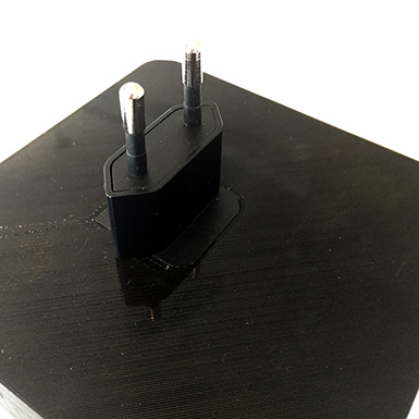
Connect Mains Supply Circuit to Plug
In this step we connect the mains supply circuit to the plug and fix the circuit in the case.
First pop the plug into the case’s plug holder. Since the copper wires are pretty rigid it is a good idea to shorten and bend them properly before soldering the wires to the mains supply circuit.
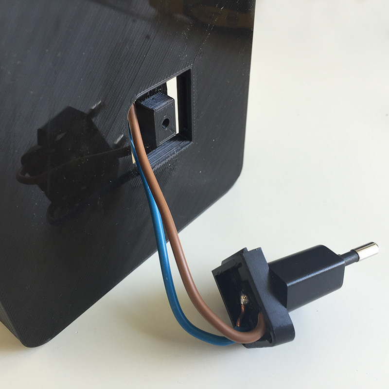


Solder the mains supply circuit’s L-conductance pad to the brown copper wire. Repeat with the N-conductance pad and the blue wire. Finally, attach the mains supply circuit to the bottom of the case. You can see the black and red 5V power supply cables on the left-hand side of the mains supply circuit. We will use these later to power the LEDs and the Arduino microcontroller.
Attach LEDs to LED Holder
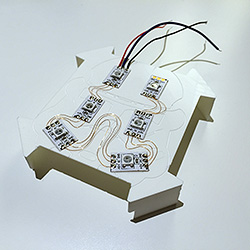 I decided to use six WS2812b LEDs and arranged them on the holder in a pattern that showed the most even illumination level during my tests. In case you’re a Lumen junkie there is enough room to cramp more LEDs on the holder. The LED strips usually come with sticky tape on their backside so gluing them on the holder is easy. After that I used 0.15mm enamelled copper wire to solder the connections between the +5V, GND and D
Prepare the Touch Sensors
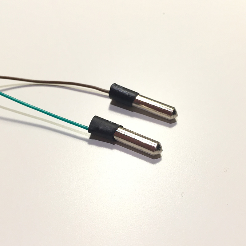 This nightlight requires two touch sensors to control its various functions. The Arduino library ADCTouch makes it very easy to add touch sensors to a project. You can connect nearly everything that changes its capacity when touched to an arbitrary analogue pin of the microcontroller and have that thing act like a touch sensor. In this project I use two small metal splints that will be stuck and glued in the drilled holes on the right-hand side of the case. To connect the splints to the Arduino I have to solder wires to them. Since they are made of stainless steel, I have to use soldering fluid again. One drop on each splint, plenty of heat, a little tin solder, and some heat shrink tubing later the two touch sensors are ready.
Wire it up!
The Fritzing breadboard view shows how the electronic components are wired up to the Arduino pro mini.
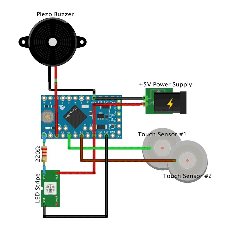
You can choose different pins on the Arduino by adjusting the Arduino Sketch accordingly.
- +5V from the power mains supply circuit goes to the VCC pin while ground is connected to the GND pin on the Arduino.
- The piezo buzzer’s negative pole is connected to the GND pin, the positive pole to pin 12.
- The upper touch sensor goes to pin A0.
- The lower touch sensor goes to pin A2.
- The view shows symbolically only one LED, not the wiring of all six LEDs. The first LED’s Din is connected via a 220 Ohm resistor to pin 10. It is usually advised to use a resistor to cover power spikes that could harm the LEDs. VSS or +5V on the LED is connected to the VCC pin on the Arduino. VDD or ground on the LED is wired to the a GND pin.
That’s how it looks like when all components have been soldered and put into place in the case.


I used hot glue to paste the Arduino and the piezo buzzer on the case. The touch sensors were easier to attach with super glue.
Light and Diffusion
We need to diffuse the light that is emitted by the LEDs so that the transparent rocket is evenly illuminated. I already had some experience with diffusion materials from another project where I tried normal paper with different grammages, frosted acrylic glass, and Ripstop. The results were ok, but not perfect. I followed a hint that white baking paper yields good diffusion results. Unfortunately, I was not able to find white baking paper; only the usual brown one. Next I tried sandwich paper (sic!) and that’s what I found to work best when it comes to LED light diffusion. Of course, it depends on what you are building and especially, how much space there is between the LEDs and the material of the boundary layer. Try different materials and find the one that best suits your needs. However, I like the sandwich paper and, thus, taped a double layer on the backside of the plate. After that, the plate is screwed to the case with four black M5x16mm counter-sunk screws. I wanted screws with no imprint on the screw head but did not pay (enough) attention to the seller’s pictures on eBay. So, always take a very close look at what you intend to buy. 😉 NB: The screws have to cut their way through the holes in the case so it can get tedious to get them in. Use appropriate force. Moreover, the screw heads were bigger than expected so I had to widen the reception holes on the lid’s front side with a hand countersink.
Code is Poetry
All that hardware does not do anything without the proper software. We need a sketch (aka program) for the Arduino pro mini so the nightlight will do the things described in the project description. Two of the used libraries are worth mentioning: The awesome FastLED library to control the RGB LEDs. And the ADCTouch library to easily turn a cable or a splint into a touch sensor. The sketch makes use of the Arduino’s inbuild non-volatile EEPROM to store modes, colors, and other stuff that can be reloaded the next time the nighlight is powered up. The most complicated part of the code is handling the touch sensors. Both sensors react to short (1st function), middle-long (2nd function) and long touches (3rd function) and trigger different functions depending on the touch durations. Sounds complicated, but is not. Or is it?
Upper sensor
- Short touch. Increase brightness of LEDs until maximum is reached (17 steps). Then turn LEDs off.
- Middle-long touch. Immediately return brightness to lowest setting, i.e., one step above zero.
- Long touch. Toggle playing Imperial March on power-up on/off.
Lower sensor
- Short touch. Change color, speed, or whatever of current lighting mode.
- Middle-long touch. Switch to next light mode.
- Long touch. Immediately switch to first light mode, i.e., fixed color.
You can find the code in my Nightlight Late-Night Edition repository on GitHub.
Ready Player One
That was a real fun project and the roket nightlight turned out to be a full success!
Sep 2016, i.f.
Great project! When will you finish the building instructions? Would love to make one. Cheers, Ron
Hi Ron,
good to hear that you like it. I will finish the instructions as soon as possible (sorry for not being more precise). 🙂
KR Axel
Tolles Nachtlicht! Hast Du noch einen Link zu den M5er Schrauben? Gruß Heiko
Hi Heiko,
suche mal bei eBay nach “m5x16 senkkopfschraube schwarz”. Da gibt’s dann eine große Auswahl passender Schrauben. Aber genau hinschauen: Viele Schraubenköpfe sind mit irgendwelchen Intarsien “verziert”. Ich wollte glatte, habe aber die Falschen erwischt.
Viele Grüße
Axel
Warum muss eigentlich jeder XXXX der meint etwas basteln zu wollen mit Netzspannung rum spielen obwohl er, wie auch dieses eigentlich sehr schöne Nachtlicht leider zeigt, nicht die geringste Ahnung hat, was er tut?
Ich habe den Beitrag in der Make gesehen und mich gefragt, wieso man sowas auch noch als Anregung zum nach bauen veröffentlicht.
Ein Gehäuse von welchen nicht einmal ansatzweise die Isoliereigenschaften bekannt sind, offen liegende Kontakte nach außen geführt deren Anschlussleitungen einmal quer über die 230V Zuleitungen zum Netzteil gehen, ohne irgend eine Schutzisolierung. (Nein, die Isolierungen der einzelnen Leitungen zählen nur als Basisisolierung und haben nicht die geringste Schutzfunktion)
Dann noch Leitungen *irgend wie* ins Gehäuse gedrückt werden und Netzspannung führende Teile auch nur *irgend wie* nicht berühren.
Bei dieser Bastelei reicht ein einziger Fehler aus den man von außen nicht sieht und 230V liegen auf einem oder beiden Stiften. Und dann viel Spaß beim dran fassen.
Nicht das Nachtlicht ist schlecht, im Gegenteil, es sieht sogar ziemlich gut aus. Sondern der sorglose und Laienhafte Umgang mit Netzspannung. Es GIBT fertige Steckernetzteile für kleines Geld, warum kann man die nicht einfach zusammen lassen und so wie sie sind verwenden.
Oder man nimmt einfach eine billige Powerbank als Versorgung, die das Ganze dann sogar noch mobil einsetzbar macht. Aber lasst einfach die Finger von der Netzspannung.
Es hat schon seinen Grund, das in (D) nur Elektrofachkräfte (und davon sind schon viele schlimm genug) mit Netzspannung arbeiten dürfen.
Frank
Hallo Frank,
Danke für Deinen Kommentar. Das ist zwar ein ordentlicher Rant, aber nüchtern und objektiv betrachtet gibt es ein paar Punkte, die für Nachbauinteressierte relevant sind. Daher habe ich Deinen Kommentar ungekürzt freigeschaltet und ihn zum Anlass genommen, an den relevanten Stellen des Artikels entsprechende Warnungen bzw. Hinweise mit aufzunehmen.
Zu den Isoliereigenschaften des Gehäuses: Informationen zu den dielektrischen Eigenschaften und der Durchschlagsfestigkeit von PLA sind schwer zu finden. Shinyama & Fujita haben das 2005 untersucht und geben in diesem Paper für PLA eine Durchschlagsfestigkeit (dielectric breakdown strenght, Eb) von 6,2 MV/cm an. Das wären 620 kV/mm und im Vergleich zur Durchschlagsfestigkeit anderer Materialien, bspw. hier (Wikipedia) oder hier, enorm hoch. Da Versuchsaufbau, -durchführung, Schichtdicke und weitere Faktoren eine wichtige Rolle spielen lassen sich die Zahlen sicher nicht 1:1 vergleichen. Interessant ist jedoch, dass in der Untersuchung von Shinyama & Fujita für ABS der Wert Eb = 4,8 MV/cm ermittelt wurde. Laut ihrer Ergebnisse ist der Eb von ABS also niedriger als der Eb von PLA. Der Kunststoff ABS wird bspw. für Netzteil-Gehäuse verwendet.
Wer fachlich etwas beitragen kann, ist herzlich zum Kommentieren eingeladen!
Beste Grüße
Axel