Mini-Frästisch Bausatz “Radagast” • schneller kommt man an keinen Mini-Frästisch
Zum Zeitpunkt dieses Blog-Eintrags sind mehr als drei Jahre vergangen seitdem ich meinen Mini-Frästisch “Gandalf” gebaut habe. Hier das zugehörige Video in meinem YouTube-Kanal. In Folge dieses Videos wurde der Designer kreith32 maximal inspiriert und hat einen Mini-Frästisch entworfen, der mit einer CNC Fräse hergestellt werden kann. Seither gibt es diesen Mini-Frästisch in der “kreith32 Edition” auf der Website von mopemaster.com zu kaufen. Der hat noch viele weitere tolle Produkte im Angebot, so bspw. das “C28”-Absaugsystem, mit dem man den ganzen unterschiedlichen Anschlüssen seiner Werkstatt-Maschinen Herr werden kann. Zurück zum Frästisch: schaut euch an, wie ich den Mini-Frästisch-Bausatz vorstelle und dann den Tisch zusammenbaue.
Bitte beachtet, dass die im Video ausgelobte Verlosung des Mini-Frästisches am 18.02.2024 endet(e). Ihr solltet aber hinreichend motiviert worden sein, euch entweder selber so einen Frästisch zu bauen oder eben den Mini-Frästisch Bausatz im Shop vom Mopemaster zu kaufen. 😉
Next Level 22W LASER mit Display zum Gravieren und Schneiden • AlgoLaser Delta
Ich habe vor vielen, vielen Jahren mal einen Diodenlaser zum Testen erhalten. Das war der Daja JL1, den es schon relativ kurz danach gar nicht mehr zu kaufen gab. Das ist auch gut so, denn das Gerät kam mit einer proprietären Software, die ständig abstürzte, nie ein Update erhielt und so krude war, dass man die Möglichkeiten der eigentlich guten Laser-Hardware nicht ausreizen konnte. Wäre alles kein Problem, wenn man den Laser bspw. mit LightBurn hätte ansteuern können. Das ging aber nicht, weil die Steuerelektronik des Lasers kein GRBL versteht. Seither liegt das Gerät zum Ausschlachten in der Asservatenkammer und ich hatte keinen Laser.
Das hat sich nun geändert, denn die Vermarktungsagentur für AlgoLaser ist auf mich zugekommen und hat gefragt, ob ich deren Flaggschiff-Modell, den AlgoLaser Delta testen möchte. Das habe ich ausführlich getan und bin dabei zu einem klaren Fazit gekommen: der Diodenlaser mit 22W ist super und wird fortan meine Werkstatt bereichern! Schaut euch das Video auf YouTube an und lasst gerne eine Like oder Abo da!
Ach ja: falls ihr euch für den AlgoLaser Delta entscheidet, wäre es natürlich super, wenn ihr über den Link in der Videobeschreibung meines Videos geht. Ihr zahlt keinen Cent mehr, aber ich bekomme eine kleine Provision, die mir hilft, den YouTube-Kanal am Laufen zu halten.
MEGA Bandschleifmaschine mit EPISCHEM Makeover und Kippfunktion • Vevor Bandschleifer
Die Bandschleifmaschine von Vevor hat es mir so angetan, dass ich ihr eine Kippfunktion und ein komplettes Makeover verpasst habe. Das Makeover hat natürlich keinerlei Einfluss auf die Funktion der Maschine. Aber ich wollte schon sehr lange mal an meine Maschinen ran, damit sie einen einheitlichen Look bekommen. Mit der Bandschleifmaschine habe ich nun den Anfang gemacht. Im Ergebnis könnt ihr im Video den “Big Black Belt Grinder” sehen, der nun im Maschinen-Fuhrpark meines Werkstatt-Reinraums den größten Hingucker darstellt. Das Auge isst schließlich mit! Solltet ihr euch auch für die anderen beiden Videos zum Bandschleifer interessieren, dann schaut einfach in die Videobeschreibung des Videos. Dort sind die anderen Videos verlinkt. Viel Spaß!
Mit diesem Video endet dann meine Bandschleifmaschinen-Trilogie. Fast versprochen!
How to utilize an old 2009 MacBook Pro with Ubuntu as a ioBroker home automation server
I was running ioBroker on a Raspberry Pi 3B with 1 GB RAM. But not for long since the Pi3 is too slow for this task. By the time of writing, roughly 2.5 yrs into Corona, Raspberry Pis have tremendously increased in price. A Pi4 with, e.g., 4 GB of RAM would surely do the job but currently costs ~150 EUR. A good alternative would be a USFF PC but in a reasonably future-proof set-up it would cost about 200-300 EUR. And then there is the question of power consumption…
But wait! I have this MacBook Pro (MBP) from 2009 lying around waiting for years and years for its second life. Perhaps this 13 year old MBP has still enough juice in it to be used as a home automation server running ioBroker?! The MacBook still boots into MacOS Yosemite (no more updates possible on this old hardware), but the battery shows “service required”. Nonetheless, it works. But MacOS Yosemite does already seem to bee “too much” for the hardware so I refrain from trying to let ioBroker run under MacOS.
Instead, the first idea was to use Proxmox as a universal virtualization environment and let ioBroker run in a virtual machine. Unfortunately, the old MacBook features a 32-bit UEFI boot loader that will not work with the 64-bit grub boot loader from Proxmox. My research showed that with some decent hacking it might be accomplished, though. Nonetheless, too much effort.
The second, and final, idea was to install Ubuntu Server LTS on the MBP. The server version has no graphical user interface and should require less ressources. Here is a quick walkthrough of the steps I have taken to install Ubuntu Server, ioBroker, InfluxDB2, and Grafana on the MBP.
Install Ubuntu Server LTS on the MBP
Create a bootable Ubuntu Server LTS installation USB Stick. The current version can be downloaded here. I used the balenaEtcher to write the Ubuntu *.iso image to a USB Stick.
Insert the USB Stick in the old 2009 MacBook Pro, fire it up, and keep the Option-key pressed during startup. The Mac’s boot menu, similar to what you can see in the following picture, should come up.
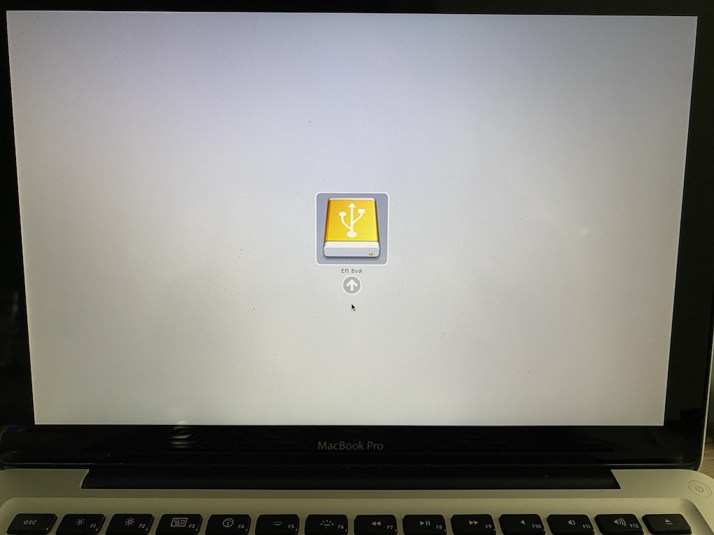
EFI Boot is the right option to chose. This will boot the Ubuntu installer from the USB Stick. Click on the arrow to do so.
The installer will come up and guide you through the process of installing Ubuntu. Steps comprise: language, keybaord, hard drive, network, name and credentials, packages, OpenSSH, etc. Since I will require remote access to the server I chose to have OpenSSH installed.
When everything has been configured, Ubuntu is installed and, depending on whether you have an internet connection, updates are downloaded automatically. A couple of minutes later, the Ubuntu Server LTS installation should be finished.
Ubuntu will reboot and greet you with its login prompt. You can log in and check for some additional updates using:
$ sudo apt update && sudo apt upgrade
Ubuntu install finished!
Set up remote access
I like to log in on remote machines using ssh with a private/public key combination. We will store a public key on the MBP and use the private key on the machine, from which we want to log in on the MBP.
First we have to create a key private/public key pair. On the Ubuntu MBP enter this. When asked to save the files, chose a proper filename, e.g. mykey.
$ ssh-keygen -t rsa -b 2048 -v
This will generate two files: mykey with your private key, and mykey.pub with the public key. Rename the private key to mykey.pem – this suffix makes it easier to see what is inside.
$ mv mykey mykey.pem
Add the public key to the authorized keys of the MBP:
$ cat mykey.pub >> ~/.ssh/authorized_keys
Transfer the private key mykey.pem to the machine where you would like to use it. If you want to store the key to a USB stick please note that Ubuntu Server does not automatically mount USB drives. Insert the USB stick and find out the stick’s device name with, e.g.
$ sudo fdisk -l
It is pretty likely that your USB stick will be /dev/sdc and its partition /dev/sdc1. If so, do the following:
$ sudo mkdir /media/usb
$ mount /dev/sdc1 /media/usb
The USB stick should be mounted and you can write the private key mykey.pem to it. Do not forget to unmount before removing the stick.
$ umount /media/usb
When you put the private key on the machine from wich you want to remotely log in to Ubuntu it is very important to make the private key read-only!
$ sudo chmod 400 mykey.pem
Now you can remotely log in like this.
$ ssh -i mykey.pem <username>@<ip-address>
Disable deep sleep and turn off display
The MBP’s lid shall be closed all the time since it is just a headless server. Thus, the MBP may not go into hibernation or deep sleep if the lid is closed. Moreover the display should turn off when the lid is closed. Everything else would be a waste of energy. Let’s handle turning off the display first.
We can edit this file
$ sudo nano /etc/default/grub
and add this line
GRUB_CMDLINE_LINUX_DEFAULT="consoleblank=60"
After saving you must update grub with
$ sudo update-grub
Reboot, and the screen should from now on always go blank after no key has been pressed for 60 seconds.
Now for the lid. We edit this file
$ sudo nano /etc/systemd/logind.conf
then uncomment the following lines and set them all to “ignore”.
HandleLidSwitch=ignore
HandleLidSwitchExternalPower=ignore
HandleLidSwitchDocked=ignore
Save, reboot, and we’re done.
Install ioBroker
Installing ioBroker is a one-liner.
$ curl -sLf https://iobroker.net/install.sh | bash -
A successful install looks like this.
ioBroker was installed successfully
Open http://<ip-address>:8081 in a browser and start configuring!
Open your favorite Web Browser and enter the above URL replacing <ip-address> with the IP address of your Pi. If your Pi uses a dynamic IP address you can find it out, e.g., with your router’s network list (list of devices that are connected to your router). If you have assigned a static IP to your Pi, as in the first optional step above, then use this one. Don’t forget to attach the port number “:8081”.
You should be greeted with ioBroker’s installation wizard welcome screen.

How to set up a headless Raspberry Pi and install ioBroker for home automation
Setting up the headless Raspberry Pi
- Get the OS Download Raspberry Pi OS from here. I chose the Raspberry Pi OS (64-Bit) lite version.
- Downloasd Flashing Tool Use a flashing tool to write the Raspberry Pi OS image to a SD card. The balneaEtcher is nice. But Raspberry’s own flasher, the Raspberry Pi Imager allows you to set a couple of options like setting a hostname, enabling SSH, configuring WIFI, and a couple of more options. I, thus, highly recommend to use the Pi Imager. If you, for some strange reason, prefer to do all this “by hand” (like I did) then just follow along the next steps.
- Flash When flashing is done, re-insert the SD card to mount it. Then open your favorite file browser and go to the root directory of your SD card (boot).
- Enable SSH Put an empty file called
ssh(yes, without suffix) into this directory. This is necessary to enable ssh so you will be able to connect to the Pi from another computer. - Configure WIFI Put a file called
wpa_supplicant.confwith the following contents in the same directory. You will have to change the country code for your country. For Germany it’s DE. For other countries: ask Google. Enter the name of your WIFI and your password. Save the file.country=DE ctrl_interface=DIR=/var/run/wpa_supplicant GROUP=netdev update_config=1 network={ ssid="name-of-wifi" psk="wlan-password" key_mgmt=WPA-PSK } - Username and Password As of April 2022 there is no standard user and password anymore in the Raspberry Pi OS image. The standard username used to be “pi” and the standard password “raspberry”. To create a username and password for the headless installation you can either write a file with the credentials in the root directory or you can use the Raspberry Pi Imager. Since you came here as a real command line nerd we will, of course, create that file. It has to be named either
userconforuserconf.txtand contains just this one line:username:password
Please consult your favorite search engine on how to create an according password. A pretty easy way is to use the following line “as is”…
pi:$6$6jHfJHU59JxxUfOS$k9natRNnu0AaeS/S9/IeVgSkwkYAjwJfGuYfnwsUoBxlNocOn.5yIdLRdSeHRiw8EWbbfwNSgx9/vUhu0NqF50
…which sets the username to “pi” and the password to “raspberry”. As soon as you are able to log into the Pi you will be able to change the password to a more secure one using the
passwdcommand.
Optional steps.
- Static IP Out-of-the-box, your Pi will receive a dynamic IP address via DHCP. I prefer to have a static IP address. Boot the Pi and log in. Since this is a headless install, you have to log in from another computer. Use the following command to edit the dhcpcd.conf file:
sudo nano /etc/dhcpcd.conf
Go to the section that looks similar to the following lines…interface wlan0 static ip_address=<your_desired_ip_address> static routers=<ip_address_from_your_router> static domain_name_servers=8.8.4.4 8.8.8.8
…and enter your desired IP address, your router’s IP address, and, optionally, your preferred domain name server(s). The ones above are the Google DNSs. Save your changes, then reboot the Pi using
sudo reboot. - Full upgrade It is usually a good idea to do a full upgrade of all applications after a fresh install by issuing the following command on your terminal.
sudo apt update && sudo apt full-upgrade -y
This process can take quite some time depending on the number of packages that need to be updated.
Installing ioBroker
Installing ioBroker is fairly easy: log in to your Pi and enter the following command on the command line. Brew some coffee. Patience required.
curl -sLf https://iobroker.net/install.sh | bash -
After the installation finished successfully you should see a message like this
ioBroker was installed successfully
Open http://<ip-address>:8081 in a browser and start configuring!
Open your favorite Web Browser and enter the above URL replacing <ip-address> with the IP address of your Pi. If your Pi uses a dynamic IP address you can find it out, e.g., with your router’s network list (list of devices that are connected to your router). If you have assigned a static IP to your Pi, as in the first optional step above, then use this one. Don’t forget to attach the port number “:8081”.
You should be greeted with ioBroker’s installation wizard welcome screen.

Enjoy!
backitup adaptor: Can’t access a NAS using CIFS (Samba)?
If you want to use the backitup adaptor to back up your iobroker installation on a network attached storage (NAS) via Samba (SMB) you may see an error message indicating that CIFS is not supported. In this case you need to install SMB support using.
sudo apt-get install smbclient
Do a
sudo reboot now
after installation and you should be good to go.
Mini Frästisch selber bauen • für Makita RT0700, Bosch GKF 12V-8 und andere
Ein Mini Frästisch bietet viele Vorteile: Er ermöglicht den stationären Einsatz einer mobilen Kantenfräse, wie bspw. der Bosch GKF 12V-8, und ist damit ideal für kleine Fräsarbeiten “zwischendurch” wie bspw. das Anfasen oder Entgraten von Werkstücken. So ein Mini Oberfräsentisch ist klein, leicht und häufig sogar mobil einsetzbar. Bis hin zur Befestigung an der Wand. In diesem Fall ist es sehr praktisch, wenn man eine French Cleat (FC) in der Werkstatt hat. Dann genügt die Befestigung einer FC-Leiste am Mini Frästisch und schon kann er an die Wand gehängt und, je nach Konstruktion, dort sogar direkt genutzt werden!
In meinem YouTube Video zum Bau eines solchen Mini Frästischs verwende ich ein passendes Set von www.mopemaster.com.
Dieses Frästisch Set kommt mit allen Teilen, um bspw. die bereits erwähnte Bosch GKF 12V-8 in einen solchen Mini Frästisch einlassen zu können. Dabei geht es insbesondere darum, dass die Kantenfräse nicht dauerhaft im Frästisch eingebaut ist, wie das häufig bei Frästischen der Fall ist. Stattdessen wird die an der Oberfräse montierte, werksseitige Fräsplatte abegeschraubt und mit einer neuen Fräsplatte aus dem Frästisch Set versehen. Dann kann die Fräse sowohl mobil als eben auch stationär im Mini Frästisch verwendet werden. Einfach großartig.
Die Frästisch Sets haben i.d.R. den folgenden Lieferumfang
- Platte zur Befestigung an Ober-/Kantenfräse
- Rahmen zum Fräsen der Aussparung
- Winkelklötze zum Halten und Nivellieren der Platte
- Reduzierringe nebst Schlüssel
- Schraubenmaterial
- 2,5er Inbus
Die Sets gibt es für die Bosch GKF 12V-8 und die Makita RT0700 in verschiedenen Farben. Frästisch-Sets für weitere Oberfräsen sind bereits in Arbeit. Beachtet, dass es für die Makita einen Klon von der Marke Katsu gibt. Auch für diesen Klon soll das Makita RT0700 Frästisch Set geeignet sein! Einfach mal im Shop vom MopeMaster stöbern.
Im Video erwähne ich auch einen Bemaßungsplan, den es hier zum Download gibt. Wichtig: Das ist keine bebilderte Schritt-für-Schritt-Anleitung, sondern eben, ja, ein Bemaßungsplan!👍🏽 • http://nptr.de/2p
Die STL vom Absaugklötzchen, das ich in den Queranschlag geklebt habe, findet ihr hier • http://nptr.de/2q
Abschließend sei noch erwähnt, dass es im Shop vom Mopemaster ausser der Frästisch Sets noch weitere sehr hilfreiche Sachen gibt, bspw. C-Profile nebst Nutensteinen oder Sterngriffschrauben, wie ich sie im Mini Frästisch Video verwendet habe.
Sonoff Basic: Tasmota Firmware flashen und mit Alexa verbinden
Das braucht man.
- 1 x Sonoff Basic, bspw. das oder das.
- 1 x FTDI Modul FT232RL, bspw. so eins hier.
- 1 x Stiftleiste mit vier Kontakten
- 4 x Female/Female Drähte
Vorbereiten des Sonoff Basic
- Sonoff Platine Mit einem Schraubendreher oder dem Fingernagel vorsichtig den Boden vom Gehäuse ablösen. Dann die Platine entnehmen. Die ist nur eingelegt und nicht verschraubt.
- Stiftleiste anlöten Oben rechts des kleinen gelben Trafos und über dem Taster (vgl. rote Markierung im Bild) befinden sich vier Lötpunkte. Dort eine Stiftleiste anlöten. Tipp: Die Stiftleiste vor dem Löten mit etwas Sekundenkleber auf der Vorderseite fixieren. Dann fällt sie beim Umdrehen nicht raus. Gelötet wird ja auf der Unterseite.

NB: Wer geschickt ist, spart sich das Löten und nimmt statt der Female/Female Drähte vier Male/Female Drähte und steckt die Male-Pins direkt in die Löcher auf der Platine. Durch Schrägstellung der Pins kann man auf diese Weise Kontakt mit den durchgeloteten Löchern herstellen. Ist mir zu frickelig, daher habe ich eine Stiftleiste angelötet.
Vorbereiten des FTDI Moduls
- 3,3V Die meisten FTDI Module erlauben es über einen Jumper oder eine Lötbrücke, die Pegelspannung auszuwählen: Entweder 5V oder 3,3V. Für den Sonoff Basic sind 3,3V die richtige Wahl. Mit 5V kann es Rauchwolken geben. Also unbedingt das FTDI Modul auf 3,3V Pegelspannung einstellen!
- Kabelage an FTDI Modul anschließen Es ist für das spätere Flashen sehr hilfreich, wenn die vier Kabel-Adern zuvor in der richtigen Reihenfolge am FTDI Modul angeschlossen wurden. Auf meinem Sonoff Basic sind die vier Anschlüsse von links nach rechts: 3.3V, Tx, Rx, GND. Die sechs Anschlüsse des FTDI Moduls, von links nach rechts: GND, o, VCC, Rx, Tx, o. NB: Die mit “o” bezeichneten Anschlüsse werden nicht benötigt.
              3,3V    Tx     Rx     GND--+
               |      |      |           |
               |      |      |           |
               |      |      |           |
GND     o     VCC     Rx     Tx     o    |
 |                                       |
 +---------------------------------------+
3,3V vom Sonoff werden mit VCC des FTDI-Moduls verbunden. GND (=Masse) mit GND. Man könnte meinen, dass Tx mit Tx und analog Rx mit Rx verbunden werden müssten. Dem ist aber nicht so: Tx steht für Transmit, Rx für Receive. Wenn das FTDI Modul via Tx etwas sendet, dann muss es von der Sonoff Platine via Rx empfangen werden. Und umgekehrt. Daher die Verdrahtung wie hier gezeigt.
Software, die für’s Flashen benötigt wird.
- NodeMCU PyFlasher Den NodeMCU PyFlasher hier runterladen. Gibt’s sowohl für den PC als auch den Mac.
- Tasmota firmware Aus dem Tasmota github repo die aktuellste Version der Firmware runterladen. Da stehen eine ganze Menge verschiedener Binärdateien zum Download bereit. Welche nehmen? Wer weder WPS noch SmartConfig noch Programm-Kode für Sensoren braucht, der wählt
tasmota-lite.bin(ehemalssonoff-basic.bin). Alternativtasmota-DE.bin, wer als Sprache deutsch möchte. Der Sonoff Basic Wifi Smart Switch hat keine Sensoren an Board, daher brauchen wir in der Firmware auch keinen Kode für Sensoren(abfragen). SmartConfig funktioniert nur im Zusammenspiel mit einer Android-App. Und WPS für die Verbindung mit dem WLAN ist auch nicht zwingend notwendig. Daher war alsotasmota-lite.binfür mich die richtige Wahl.
Flash, ahaaaa, saviour of the Universe! Jetzt wird die Tasmota Firmware auf den Sonoff Basic geflashed!
- FTDI Modul an Mac/PC anschließen Das FTDI Modul per USB Kabel mit dem Mac/PC verbinden. Meistens leuchtet irgendeine LED auf dem Modul, dann hat das Dingen Strom. Beim ersten Anstecken kann es sein, dass noch eine Treiber-Software installiert werden muss. Das sollte Euer Betriebssystem automatisch erledigen. Jetzt ist das Modul einsatzbereit.
- NodeMCU PyFlasher Den NodeMCU PyFlasher starten und konfigurieren: Zunächst den Serial Port auswählen. Auf dem Mac ist das sowas wie cu.usbserial-xxxx, auf dem PC ein COM-Port. Dann bei “NodeMCU firmware” mit dem Browse-Button die zuvor runtergeladene Tasmota Firmware Datei auswählen. Die Baud rate muss auf 115200 eingestellt werden. Der Flash Mode ist abhängig vom Sonoff Modultyp; für den Basic ist DOUT die richtige Wahl. Abschließend “Erase flash” auf yes setzen. Damit ist der PyFlasher fertig konfiguriert.

- Flashen Zum Flashen wie folgt vorgehen: Den Taster auf der Sonoff Platine drücken und gedrückt halten. Während dieser gedrückt ist, dass vieradrige vom FTDI-Modul kommende Kabel mit seinen vier Buchsen auf die eingelötete Stiftleiste der Sonoff-Platine aufstecken. Einen Moment warten und erst dann den Taster loslassen. Damit ist die Sonoff Platine im Flash-Modus. Jetzt im PyFlasher den Button “Flash NodeMCU” anklicken. Der Flash-Vorgang sollte starten und sich nach nicht allzu langer Wartezeit mit einem “Firmware successfully flashed.” zurückmelden.
- Neustart Die Drähte von der Stiftleiste des Sonoff abziehen und wieder verbinden. Wenn jetzt die grüne LED blinkt, hat alles geklappt. Wahrscheinlich.
Den Sonoff mit dem heimischen WLAN verbinden.
- Die LED blinkt Das Blinken der LED zeigt an, dass der Sonoff Basic nun versucht sich mit einem WLAN Netzwerk zu verbinden. Noch kennt er aber weder den Namen des eigenen WLANs noch dessen Passwort. In diesem Zustand spannt der Sonoff Basic einen eigenen Access Point auf. Den brauchen wir im nächsten Schritt.
- Mit Sonoff per WLAN verbinden Um dem Sonoff Name und Passwort des eigenen WLANs mitzuteilen, müssen wir uns erst mit dem WLAN Netzwerk, dass er selber aufspannt, verbinden. Also über die Netzwerk-Einstellungen vom Mac oder PC mit dessen WLAN, das irgendwie “sonoff-XXXX” heißt, verbinden.
- 192.168.4.1 Je nach Betriebssystem öffnet sich nun ein Browser-Fenster, in dem die Zugangsdaten des eigenen WLAN Netzwerkes eingegeben werden können. Sollte sich kein Fenster öffnen, dann einfach im Browser die IP-Adresse
192.168.4.1eingeben.
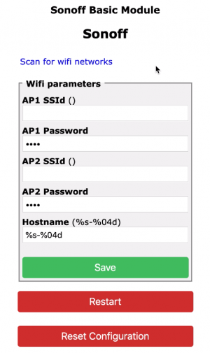 In der Regel wird es genügen, den Namen des eigenen Netzwerkes im Feld “AP1 SSId” und das zugehörige Passwort im Feld “AP1 Password” einzugeben. Nach Klick auf den Save-Button werden die Einstellungen im Sonoff gespeichert und dieser neu gebootet.
Und das war’s. Nach dem Reboot sollte sich der Sonoff Basic Wifi Smart Switch automatisch mit dem heimischen Netzwerk verbinden. Leider kann man dem Sonoff nicht ansehen, ob er sich denn auch erfolgreich mit dem eigenen WLAN verbunden hat. Mit der IP-Adresse 192.168.4.1 kann man den Sonoff jetzt nicht mehr ansprechend, da das vom Sonoff aufgespannte eigene “sonoff-XXXX” Netzwerk nicht mehr existiert. Vorausgesetzt, die Verbindung zum eigenen WLAN Router war erfolgreich, dann hat der Sonoff jetzt eine andere vom WLAN Router per DHCP vergebene IP-Adresse. Wenn wir diese kennen, können wir sie im Browser eingeben und auf die Konfigurationsoberfläche des Sonoff gelangen. Aber wo bekommen wir diese IP-Adresse her? Hier zwei mögliche Wege.
- Liste verbundener Geräte Wenn man sich in die Admin-Oberfläche seines WLAN Routers einwählt, kann man üblicherweise (irgendwo) eine Liste der mit diesem Router verbundenen Geräte einsehen. Und genau in dieser Liste müsste auch der Sonoff Basic zu finden sein. Manche Geräte und/oder Hersteller werden von den WLAN Routern erkannt und mit Namen ausgewiesen, das vereinfacht die Suche. In meinem Router wird der Sonoff Basic nicht benamt, daher kann es mitunter nötig sein, verschiedene der angezeigten IP-Adressen im Browser einzugeben, bis man die richtige gefunden hat.
- Terminal Programm Wenn der Sonoff Basic mit dem FTDI Modul verbunden ist, kann man mit einem Terminal-Programm direkt auf den Sonoff zugreifen. So lassen sich Parameter auslesen oder der Sonoff über eine Vielzahl an Kommandos konfigurieren; im Tasmota-Github sind alle verfügbaren Kommandos gelistet.
Für den PC wird als Terminal-Programm gerne das kostenlose Termite benutzt. Für den Mac gibt es bspw. das ebenfalls kostenlose CoolTerm. Im Terminal-Programm muss zunächst der Port ausgewählt werden über den das FTDI Modul mit dem PC/Mac verbunden ist, also COMx oder cu.usbserial-xxxx. Dann noch die Baud rate auf 115200 setzen und, im Falle von CoolTerm, den Line Mode einschalten. Dann ggfs. mit dem Sonoff verbinden (bspw. via “Connect” o.ä.) und wir sollten Zugriff auf die Tasmota Firmware auf dem Sonoff Basic haben.
Als ersten Test im Terminal-Programm den Befehl “status” gefolgt von Return eingeben. Wenn dann etwas im Terminal-Programm ausgegeben wird, hat die Verbindung geklappt!
Jetzt wollen wir die IP-Adresse herausbekommen. Mit dem Befehl “restart 1” wird der Sonoff gebootet. Und dann sollten Informationen im Terminal ausgegeben werden, u.a. die IP-Adresse, mit der der Sonoff mit dem WLAN verbunden ist; vgl. Screenshot.

Jetzt kennen wir die IP Adresse und können diese in der Adress-Zeile unseres Browsers eingeben. Dort sollte uns dann der Startbildschirm des Sonoff Basic begrüßen.
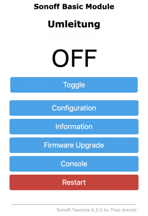
Fertig! Nun kann man den Sonoff Basic Wifi Smart Switch bspw. über den Browser eines Handys steuern. Oder auf einem Android-Gerät eine passende App dafür installieren. Oder den Switch ins heimische Home Automation Netz einbinden.
Oder ihn per Alexa steuern. Wie das geht, zeige ich in meinem Sonoff Basic: Tasmota Firmware flashen und den Wifi Smart Switch mit Alexa verbinden HD Video auf YouTube.
Viel Spaß!
7 easy steps to set up OctoPrint on Raspberry Pi
If you want to remotely control your 3D printer, OctoPrint might be your choice. This is a very, very short seven-step instruction to show, how OctoPrint is set up on a Raspberry Pi. No pictures, no videos, just the plain vanilla facts.
- Download Octoprint from octoprint.org.
- Flash Octoprint image Use, e.g., Etcher from balena to flash the Octoprint image on a micro SD card. Do not format the SD card even if your operating system asks you to do so. Just flash the Octoprint image on the SD card.
- Setup Wifi Re-insert the SD card in your SD card reader. Edit the file
octopi-wpa-supplicant.txtin theboot/directory. Use an appropriate editor to do this. There is a plethora of information out there that explains why this is important; in case of doubt please use a search engine.
There are two sections in the file that are relevant:### WPA/WPA2 secured #network={ # ssid="" # psk=" " #} # Uncomment the country your Pi is in ... #country=GB # United Kingdom #country=CA # Canada #country=DE # Germany #country=FR # France country=US # United States Take care that you uncomment the country you’re living in and comment out the one that was previously uncommented. Take even more care that you do not only enter the ssid and your password in the WPA/WPA2 section but that you also uncomment the lines starting from
networkdown to and including the line with the single closing brace. - Enable SSH To log into your Pi via SSH you may need to enable it first. Do this bei putting an empty file named
ssh(without any extension) in theboot/directory (if it does not exist already, of course). A simple way to create an empty file is to use the following commandtouch ssh. - Fire up the Octopi Put the SD card into your Pi, connect a power source and fire it up! Wait approx. 90 seconds until the boot process is completed.
- Log in using SSH Use ssh to remotely log into your Pi*. The Octopi will be reachable either by using its IP address (that you will have to find out, e.g., by looking into your router’s attached devices section) or via
octopi.local. The latter requires Bonjour to run properly on your computer. Assumed you know the IP address, use this terminal command to log in:
SSH pi@<ip-address>
You will be asked to confirm a certificate. Type ‘yes’ followed by a return. Then enter the password. The standard password israspberry.
(*Mac users will usually use terminal, Windoze users may want to use PuTTy as a SSH-client.) - Change password Change the standard password using the command
passwd. You will be asked to enter the old password then twice the new one. Done. - Access OctoPrint via web browser Start a web browser and enter
http://octoprint.local(requires Bonjour service) orhttp://<ip_address>. You should see the OctoPrint interface and a setup wizard pop up. This page has a table with settings for many common 3D printers. Follow along and be sure to set up a username and password for your OctoPrint.
Now open up the connection panel on the left. With the options set to “AUTO” hit Connect. If the connection was successful congratulations – you’ve successfully set up OctoPrint!
Optional steps.
- Static IP Out-of-the-box, your Pi will receive a dynamic IP address. I prefer to have a static IP address.
When the Pi is booted and you are logged in, use the following command on the command line to edit the dhcpcd.conf file:
sudo nano /etc/dhcpcd.conf
Go to the section that looks similar to the following lines…interface wlan0 static ip_address=
static routers= static domain_name_servers=8.8.4.4 8.8.8.8 …and enter your desired IP address, your router’s IP address, and, optionally, your preferred domain name server(s). The ones above are the Google DNSs. Use
sudo rebootto reboot the Pi. - Full upgrade Consider a full upgrade of your intallation by issuing the following command on your terminal.
sudo apt update && sudo apt full-upgrade -y
That could take quite some time.
How to run Netgear ProSafe Utility on MacOS
Netgear is offering his switch management software “ProSafe Plus” for Windows. And for Windows only. Well, they just might have not noticed that there is at least one other very popular operating system in the market. Such things happen.
To still run ProSafe on a Mac and avoid the overhead involved by installing hardware virtualizing suits like “Parallels Desktop” or “VirtualBox”, I tried to use the compatibility layer software WINE to run ProSafe.
WINE
WINE requires XQuartz first, then Wine for MacOS can be installed. After that you can right click an arbitrary Windoze *.exe file and “open with…” Wine. Unfortunately, the ProSafe Plus Utility did not install smoothly. Had to restart the installation process a couple of times but could start the ProSafe Utility only once. Digging into Wine’s website winehq.org you will find that other users already reported about problems with the installation of ProSafe. To sum it up: No easy way this time. Let’s do it the hard way.
VirtualBox
The hard way means that you will have to use a hardware virtualizer like VirtualBox or Parallels Desktop. And, apparently, you will need Windoze. Luckily, I had an old Windoze 7 installation CD lying around. The first step is to install the free virtualizer VirtualBox by Oracle. The installation process is pretty straightforward and to just run the ProSafe Utility you should be fine with the standard settings suggested by the installer.
You will, most likely, have assigned an ISO-Image of your copy of Windoze during installation. After VirtualBox has been installed, start the Windoze Virtual Machine and get your copy of Windoze installed in the Virtual Machine. That might take some time. After successful installation of Windoze you can reboot, log into your Windoze account and install Netgear’s ProSafe Utility.
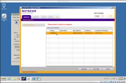
After installation of the ProSafe Utility fire it up and, if all went well, you might see a screen similar to the following one. The ProSafe utility scans the network and will list all discovered switches. My switch, a GS108PEv3, hast been found and I am, finally and after all that hassle, ready to configure the switch.
Nightlight Late-Night Edition
 This project powers electronic components (5V) with a mains supply circuit (230V > 5V) that is connected to a power plug (230V). If you are going to build this, make sure that you know what you do. In case of doubt, consult a skilled person that is familiar with mains voltage or use a safe power source like a line adapter or batteries.
tl;dr A nightlight based on a reworked Thingiverse design with Arduino-controlled LED light effects, touch sensors, and a piezo buzzer humming the first notes from the Imperial march. Watch the video to see it in action. Detailed instructions start below video.
Bragging rights
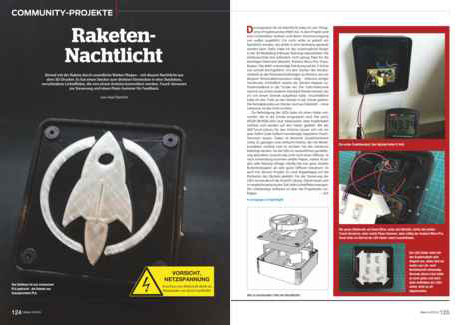 The rocket nightlight was presented in the German MAKE magazine 06/2016 as a community project. Thank you! 🙂
The link or a click on the picture take you to the table of contents of issue 06/2016. If you have questions concerning this project do not hesitate to contact me! <foobar@zeropage.io>
Project Description
You can find a great design for a LED nightlight with various emblems or logos like Stormtrooper, Superman, Punisher, etc. on Thingiverse. This design is based on a 3D printed case with a transparent and extruded inlay of the emblem/logo in the lid. The case has a hole on the backside to have an external power supply feed the internal light source, e.g., an RGB light stripe or similar.
I reworked this design to create a nightlight that
- does not need an external power supply, i.e., has a plug and can be directly plugged into a wall socket
- has touch switches to easily adjust the brightness, light effects (or modes), colors etc.
- uses a piezo buzzer to acknowledge touch switch triggers and to play the first notes from the Imperial March when plugged into a socket (a little annoying, but can be switched off;-)
- utilizes a mounting platform for six RGB LEDs that can be easily inserted into the case
- fixes some minor issues in the original design (displaced inlay and mounting hole)
- comes with a variety of light effects like fixed colors, strobe, or cyclone chase
Payload
1 x Arduino Pro Mini 5V 16MHz // Merchants on eBay offer a plethora of pro minis. Take care when ordering: The pro mini is available as 3,3V and 5V as well as 8MHz and 16MHz versions. Moreover: Many vendors are located in China; shipping may take a long time to your home country.
1 x Piezo buzzer // One of these (eBay) should work.
1 x Power supply // I used this EMSA050120, 5 V-/1,2 A from Pollin to harvest the mains supply circuit and the plug.
4 x 3D printed part // These parts comprise a case, an LED holder, a plate (or lid) and an emblem/logo. You will find the 3D templates as STL files on Thingiverse.
6 x RGB LED // The WS2812b have a nice color range and are usually cheapest when bought as an LED stripe. I had some spare LEDs from another project. You can order them on eBay or here (1m stripe, Roboter Bausatz Shop).
4 x M5, 16mm counter-sunk screw
1 x Software // The software for the Arduino is available in my Nightlight Late-Night Edition repository on GitHub.
Moreover a Dremel or similar to cut open the mains adapter, pliers, rasps, wires, some metal splints for the touch sensors, and, of course, a soldering iron.
Nightlight 3D Parts
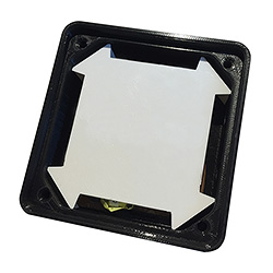
The nightlight consists of four 3D printed parts; cf. the sandwich picture showing the different layers.
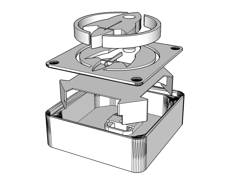
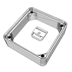
From bottom to top: 1) Case to host the mains supply circuit, Arduino pro mini, piezo buzzer, LEDs, touch switches, cables, and the plug. 2) LED holder. 3) The top plate and 4) the extruded emblem inlay.
3D Part 1: The Case
The case from the original design was only 13mm high (inner height) and, thus, not tall enough to host the electronic parts. I had to import the STL file into SketchUp and stretch the case on the z-axis to an inner height of 25mm. That gave me just enough space to squeeze the LED holder above the mains supply circuit into the case and still have 2 or 3mm distance from the top plate. The more space you have between the LEDs and the plate, the better the light will be diffused. But I did not want the nightlight to be more bulky than necessary so 25mm inner height had to suffice.
Increasing the height was the easy part. Designing the plug holder on the backside of the case was more difficult. I first measured the dimensions of the plug as precise as possible, then started to design a plug holder with SketchUp.
It took a couple of iterations and an according number of test prints until, finally, the plug snapped into the plug holder with a satisfying “click”. The plug fits so tight that I consider it to be unremovable without destroying the case. And I may add that this is by design since we are dealing with 230V AC power and the nightlight must be impenetrable by adventurous kid’s hands.
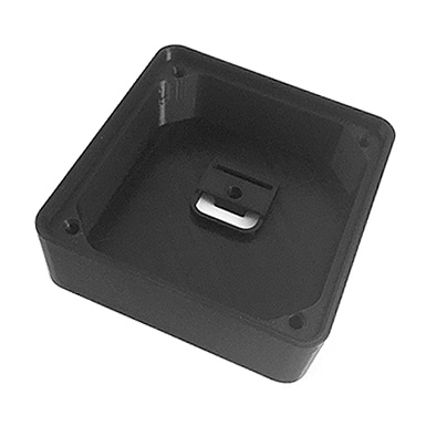
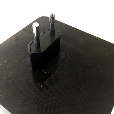
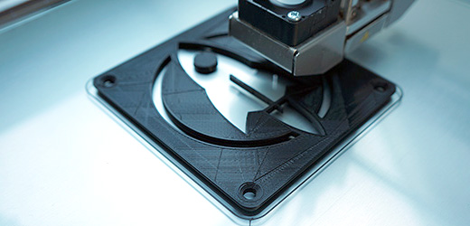
The case was printed with black REC PLA at 210°, bed temperature 60°, no support, 0.16mm height, 1.2mm wall thickness, and 66% infill. It depends on your 3D printer’s bridging abilities if the plug holder will be ok without support. If unsure, print the case with support turned on.
3D Part 2: The LED Holder
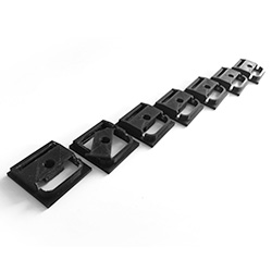
I wanted the LEDs in the nightlight to be on a planar surface to get an even illumination. The idea was to construct an LED holder in SketchUp that tightly fits into the case without gluing, is rather stable, and has legs to stand on. The images show what I came up with.
Luckily, the LED holder nearly immediately matched all of the above mentioned criteria. I chose white innofil3D PLA for the print since a white background looked best behind the semi-transparent inlay.
3D Part 3: The top Plate
The plate was printed with black REC PLA and the same print parameters as for the case (210°, bed temperature 60°, no support, 0.16mm height, 1.2mm wall thickness) except that infill was set to 100%. I did not want any light to escape through the plate. With a proper number of top and bottom layers 100% infill with black PLA might be an extreme overkill but I played it safe.
With 100% infill the plate came out rock solid which has another advantage: Some parts might need to be sanded so that the extruded emblem/logo wil fit into the plate. The more solid your parts, the better they can be sanded.
3D Part 4: The Emblem/Logo
The extruded rocket inlay was printed with transparent innofil3D PLA. You will notice that “transparent” is in no way comparable to acrylic glass or alike. Moreover, parts printed with this PLA look yellowed; like they have been exposed for too long in the sun. Nonetheless, this kind of transparency is the best you can get with current fused deposition modelling (FDM) based desktop 3D printers and PLA. Nylon and other filament materials might yield better results but they are more difficult to print and handle.
Infill was set to 22%. You will see the honeycomb pattern, or whatever type of infill you chose in your slicer, with such a low infill value. But more infill also means losing transparency. I was fine with 22%.
Avengers assemble!
Let’s put the hardware together.
Complete the Plate
 The transparent emblem/logo has to be merged with the plate. Depending on the design there might be a couple of “loose” parts from the plate print that need to be inserted into the emblem/logo first. Rasps and sanding paper are your best friend in this step since the parts will most likely not fit straight off the 3D printer. While 3D prints are usually pretty nice, there are limits to the precision you can expect from FDM prints. The rocket has only one loose part which is the round window. That one is pretty easy to insert. If not, rasp and apply mild force. Do not apply too much pressure to the small parts – they might break or damage the plate. If in doubt, sand more and re-try often. It will finally fit. If all loose parts are pushed in the emblem/logo you will want to merge the emblem/logo with the plate. That might need some sanding too. The small and tall middle wing of the rocket will most likely need some sanding. Be very careful since it can break off easily. Carefully push the transparent part into the plate. A vise or a hammer might come in handy, depending on how brave you are. This step requires patience.
Disassemble the Power Supply
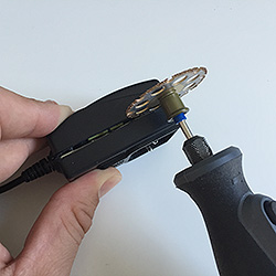
As mentioned in the Payload-section I used a very cheap EMSA050120 power supply from Pollin to harvest the mains supply circuit and the plug. The case turned out to be very intractable and successfully resisted my attempts to pry it open it with a screw driver or pliers. I could have tried to pop it open in the vise but did not want to risk damaging the PCB/electronics inside. Well, let’s mill it open – Dremel time!
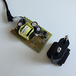
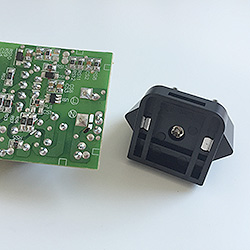
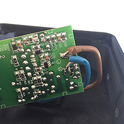
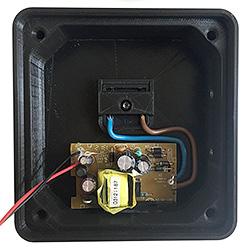
Caveat: Always mill with safety glasses and use protective gloves. The picture is just for demonstration purposes. Milling plastic produces foul-smelling, and most likely toxic, fumes. Do it outdoors. The picture in the middle shows the mains supply circuit along with the plug. In the next picture you can see the backside of the supply circuit with the big L- and N-conductance pads on the right-hand side of the PCB.
Solder Wires on Plug
The plug will be connected with solid copper cables to the L- and N-conductance pads of the mains supply circuit.
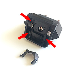
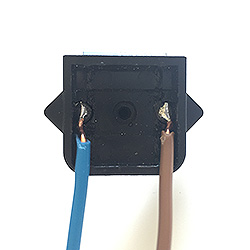
Before we can solder the cables two small plastic bars have to be removed from the plug. I use pliers to simply break them off. After that I start to solder the cables on the plug’s connection pads (to the left and right of the middle screw). Or I tried because this turns out to be an epic soldering fail. I try a dozen times but can’t get the, sorry, GODDAMMIT cables to solder-join with the pads. The pads literally refuse to be soldered! But resistance is futile and a couple of search engine queries later I seem to be wiser: The pads are made of stainless steel which is pretty hard to solder with normal tin-solder. If not impossible at all. What I need is soldering fluid, something like this (Conrad).
If you read the soldering fluid’s hazard notes, well, you do not really want to use this stuff: Serious chemical burns of skin and eyes, irritating to the respiratory system, and so on and so forth. Zinc chloride is no fun. Keep away from children! After some more failed attempts even with the soldering fluid I learned that the pads need much more heat to join forces with the cables than I was used from soldering usual electronics stuff. So, finally, I got two nice solder joints. FTW!
Drill Holes for Touch Sensors
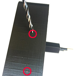 It is always a good idea to think before you act. And I wish I’d done that before printing the case since I forgot to add two 4mm holes for the touch sensors on the right-hand side of the case! Facepalm! Printing the case again just because two holes were missing was not an option. But we are not only apt with additive but also with subtractive manufacturing: I drill the holes with a 3mm wood drill and get a perfect diameter after some minor rasping. PLA is fairly easy to drill, e.g. compared to acrylic glass. But you may have to lift the drill from time to time to remove excess plastic. Wood drills are designed to automatically forward the excess wood to the top of the drill and out of the drill hole. When you drill PLA or other plastic materials it tends to melt and get stuck on the drill. The slower you drill, the better. Applying some drops of water or sewing-machine oil is said to help (not tried so far).
Connect Mains Supply Circuit to Plug
In this step we connect the mains supply circuit to the plug and fix the circuit in the case.
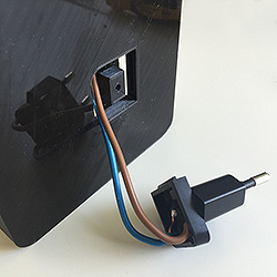
First pop the plug into the case’s plug holder. Since the copper wires are pretty rigid it is a good idea to shorten and bend them properly before soldering the wires to the mains supply circuit.
Solder the mains supply circuit’s L-conductance pad to the brown copper wire. Repeat with the N-conductance pad and the blue wire. Finally, attach the mains supply circuit to the bottom of the case. You can see the black and red 5V power supply cables on the left-hand side of the mains supply circuit. We will use these later to power the LEDs and the Arduino microcontroller.
Attach LEDs to LED Holder
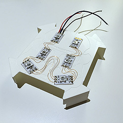 I decided to use six WS2812b LEDs and arranged them on the holder in a pattern that showed the most even illumination level during my tests. In case you’re a Lumen junkie there is enough room to cramp more LEDs on the holder. The LED strips usually come with sticky tape on their backside so gluing them on the holder is easy. After that I used 0.15mm enamelled copper wire to solder the connections between the +5V, GND and D
Prepare the Touch Sensors
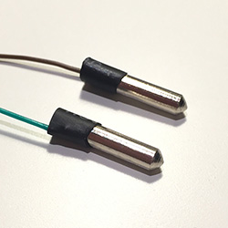 This nightlight requires two touch sensors to control its various functions. The Arduino library ADCTouch makes it very easy to add touch sensors to a project. You can connect nearly everything that changes its capacity when touched to an arbitrary analogue pin of the microcontroller and have that thing act like a touch sensor. In this project I use two small metal splints that will be stuck and glued in the drilled holes on the right-hand side of the case. To connect the splints to the Arduino I have to solder wires to them. Since they are made of stainless steel, I have to use soldering fluid again. One drop on each splint, plenty of heat, a little tin solder, and some heat shrink tubing later the two touch sensors are ready.
Wire it up!
The Fritzing breadboard view shows how the electronic components are wired up to the Arduino pro mini.
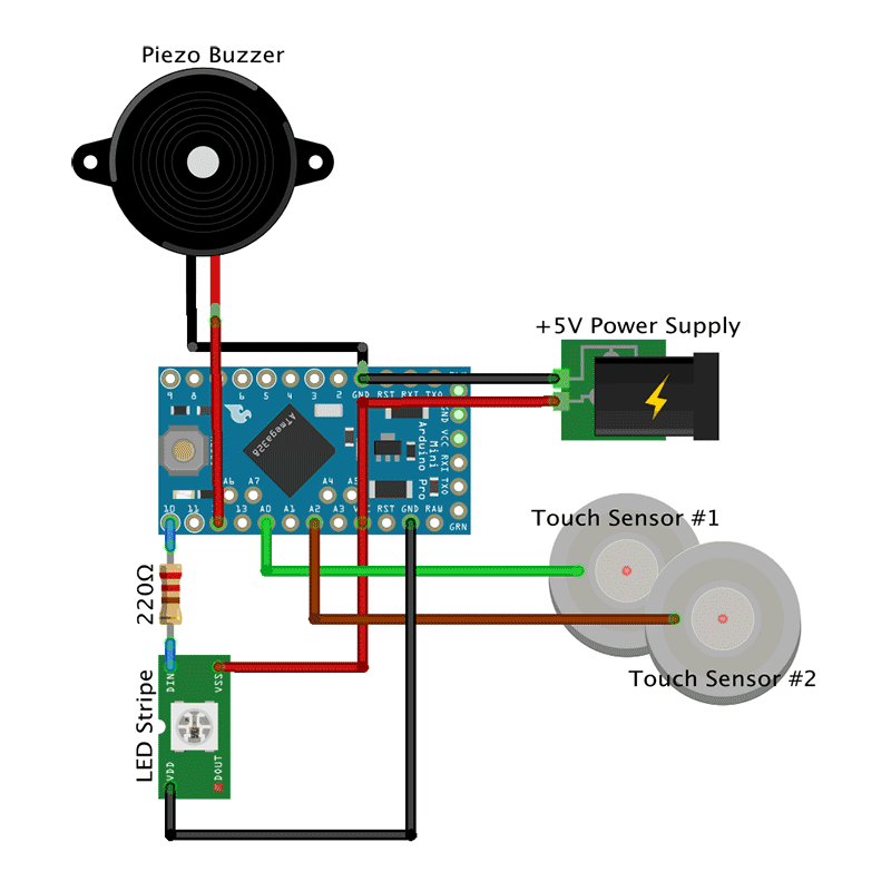
You can choose different pins on the Arduino by adjusting the Arduino Sketch accordingly.
- +5V from the power mains supply circuit goes to the VCC pin while ground is connected to the GND pin on the Arduino.
- The piezo buzzer’s negative pole is connected to the GND pin, the positive pole to pin 12.
- The upper touch sensor goes to pin A0.
- The lower touch sensor goes to pin A2.
- The view shows symbolically only one LED, not the wiring of all six LEDs. The first LED’s Din is connected via a 220 Ohm resistor to pin 10. It is usually advised to use a resistor to cover power spikes that could harm the LEDs. VSS or +5V on the LED is connected to the VCC pin on the Arduino. VDD or ground on the LED is wired to the a GND pin.
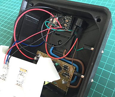
That’s how it looks like when all components have been soldered and put into place in the case.
I used hot glue to paste the Arduino and the piezo buzzer on the case. The touch sensors were easier to attach with super glue.
Light and Diffusion
We need to diffuse the light that is emitted by the LEDs so that the transparent rocket is evenly illuminated. I already had some experience with diffusion materials from another project where I tried normal paper with different grammages, frosted acrylic glass, and Ripstop. The results were ok, but not perfect. I followed a hint that white baking paper yields good diffusion results. Unfortunately, I was not able to find white baking paper; only the usual brown one. Next I tried sandwich paper (sic!) and that’s what I found to work best when it comes to LED light diffusion. Of course, it depends on what you are building and especially, how much space there is between the LEDs and the material of the boundary layer. Try different materials and find the one that best suits your needs. However, I like the sandwich paper and, thus, taped a double layer on the backside of the plate. After that, the plate is screwed to the case with four black M5x16mm counter-sunk screws. I wanted screws with no imprint on the screw head but did not pay (enough) attention to the seller’s pictures on eBay. So, always take a very close look at what you intend to buy. 😉 NB: The screws have to cut their way through the holes in the case so it can get tedious to get them in. Use appropriate force. Moreover, the screw heads were bigger than expected so I had to widen the reception holes on the lid’s front side with a hand countersink.
Code is Poetry
All that hardware does not do anything without the proper software. We need a sketch (aka program) for the Arduino pro mini so the nightlight will do the things described in the project description. Two of the used libraries are worth mentioning: The awesome FastLED library to control the RGB LEDs. And the ADCTouch library to easily turn a cable or a splint into a touch sensor. The sketch makes use of the Arduino’s inbuild non-volatile EEPROM to store modes, colors, and other stuff that can be reloaded the next time the nighlight is powered up. The most complicated part of the code is handling the touch sensors. Both sensors react to short (1st function), middle-long (2nd function) and long touches (3rd function) and trigger different functions depending on the touch durations. Sounds complicated, but is not. Or is it?
Upper sensor
- Short touch. Increase brightness of LEDs until maximum is reached (17 steps). Then turn LEDs off.
- Middle-long touch. Immediately return brightness to lowest setting, i.e., one step above zero.
- Long touch. Toggle playing Imperial March on power-up on/off.
Lower sensor
- Short touch. Change color, speed, or whatever of current lighting mode.
- Middle-long touch. Switch to next light mode.
- Long touch. Immediately switch to first light mode, i.e., fixed color.
You can find the code in my Nightlight Late-Night Edition repository on GitHub.
Ready Player One
That was a real fun project and the roket nightlight turned out to be a full success!
Sep 2016, i.f.


