3D printed resistor storage box with wall mount
Quite some time ago I ordered five E12 series resistors that I received in a plethora of plastic bags. One plastic bag for every resistor value. And since there are 12 resistors in each series, I had 60 plastic bags with resistors ranging from 10 Ohm to 820 kOhm lying around. That is the antitheses of orderliness and usability.
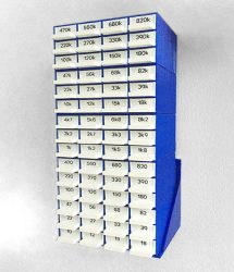
Browsing Thingiverse I came across this nice little resistor storage box.
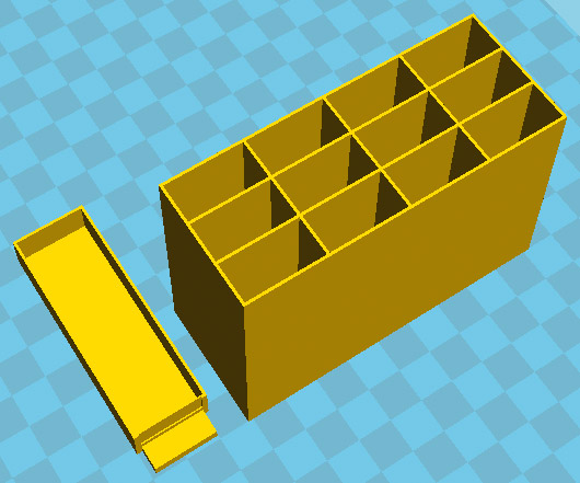
Each box has 12 drawers to hold all resistors from one E12 series. Printing five (actually six with a test print) boxes and 60(!) drawers was a lengthy process.
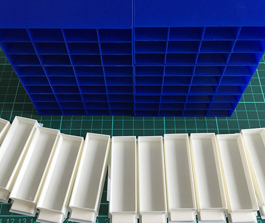
The result is ok. Though deliberately choosing a low print quality for the drawers (=less printing time) combined with warped backsides of the boxes required some reworking with a cutter blade and sanding paper. I use super glue to stack the boxes on top of each other and put the resistors into their drawers.
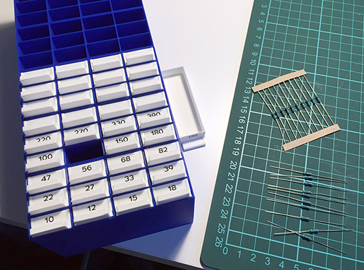
The drawers have a 17x6mm cavity at the front that can be used as a label field. Labeling the drawers is mandatory since there is not much sense in putting resistors into drawers without knowing which resistor has which resistance… 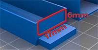 Unless, of course, you like to compare the color rings with a resistor color table. It would be an interesting idea to build a simple Arduino-based auto-ranging ohmmeter and attach it to the top or bottom of the storage box phalanx; note to self for a later project. A label writer with 6mm tapes helps in creating and easily attaching the labels. Another solution would be to print, cut, and glue the labels. Hand writing might be an option, or you could even 3D print the labels which would be yet another fine Sisyphean task.
Now that the drawers have been labeled and all resistors are stored in their according drawer we have to think about where to place the resistors. When simply put on a table it will be hard to read the resistances of the drawers at the bottom of the stack of boxes. Moreover, the drawers can easily be pushed and pulled which is good for accessing the resistors but bad if the stack of boxes is jerked and the drawers start to slide out by themselves. Or, even worse, the box gets knocked over and spills all resistors on the table and floor. In order to properly read the labels I would like to attach the stack of boxes to the wall at eye level. And I want the boxes to be slightly tilted upwards so the drawers will not slide out by themselves.
Let’s create a wall mount with SketchUp!
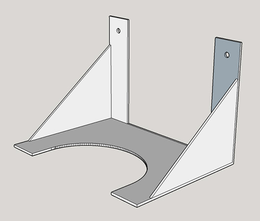
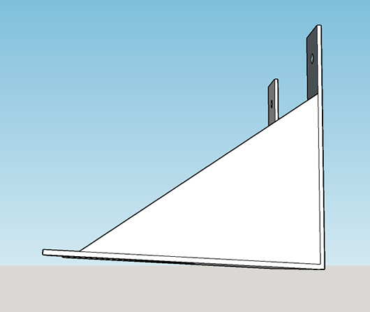
You can download the STL file here. The next picture shows the box holder screwed to the wall. The holder looks distorted but this is due to the chosen perspective for the photography.
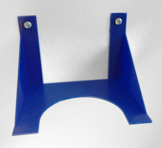
Finally, the stack of resistor boxes is super glued to the holder. Major achievement: “order and stability in our [resistor] country.”

“Resistance is futile!”
i.f.

Lord Overhaul: How to repair a coffee grinder’s broken bean hopper
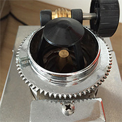
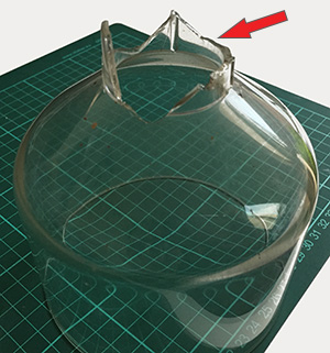 My coffee grinder’s outlet experienced some sort of non-graceful degradation due to 50% operating error and 50% faulty design: A screw that was intended to fix the bean hopper to the coffee grinder’s base crushed into the outlet and broke it. In the aftermath of this unhappy event pieces started to brake away from the bean hopper’s outlet impairing its functioning.
What now? A new bean hopper would cost about 20,- €. Pretty expensive, and, BTW, where is the fun in that? “Stay back boy! This calls for divine intervention! … I kick ass for the Lord!” – Father McGruder from Brain Dead, 1992. Time for Lord Overhaul’s sliding caliper, some CAD (Computer-Aided Design) Voodoo, and a 3D printer to make a spare funnel for the bean hopper!
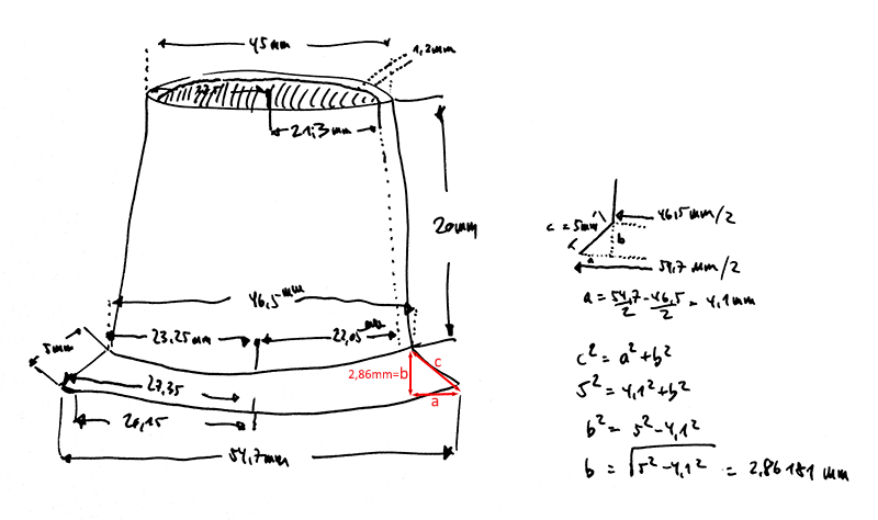
I use the caliper to measure a couple of things to get the dimensions of the funnel as exactly as possible. The most measurements are quit simple being either diameters or lengths. There is only one measurement that is a bit trickier: The correct slope of c is crucial for the funnel to neatly adapt to the bean hopper. The length of c can be measured easily, and a is the difference between the diameters of the outmost circle and the one beneath it. Since I can not measure the height b reliably, Pythagoras’ theorem comes to the rescue to calculate b. Confer the picture for an incredibly detailed and clearly arranged sketch. LOL
Now for the fun part: I need a 3-dimensional digital representation of the funnel and nearly immediately fail to design an according shape in SketchUp. A fool with a tool is still a fool! In other words: Non-sufficient skills in a) CAD and b) SketchUp. Back to school, YouTube is your friend. After viewing some SketchUp howto videos about funnel drawing I came across this one by Ivor O’Shea.
Ivor describes a method using an outline and the “follow me” tool. After some trial and error I could finally come up with an outline for the bean hopper funnel that looked like it could work.

Picture one shows the outline of my funnel with the dimensioning derived from the hand-drawn sketch (click picture to enlarge). I erased all snap lines drawn with the tape measure tool for clarity. Nonetheless, you definitely need snap lines for this method. In picture two you can see the “follow me” tool in action. The circle on the ground is only needed as a helper for the “follow me” tool and can be erased afterwards. By following the outline around the circle to a full 360° we get a complete funnel; cf. picture three.
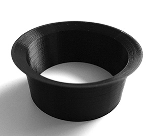 SketchUp exports to STL which is then loaded into the slicer who in turn produces the *.gcode file that is sent to the 3D printer. After only two failed 3D prints due to wrong slicer settings and issues with warping and elephant foot the third print was successful. A nice black funnel that looks like it could fit perfectly on the bottom of the bean hopper. But before the funnel can be attached the bean hopper needs some precision work: The mortal remains of the old funnel need to be removed.
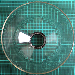
I first use a ripsaw to cut off the protruding parts of the old funnel from the bean hopper. Then I use a cutter blade to remove bumps and edges to get an even surface. Finally, I remove small ridges with sand paper.  There is nothing I can do about the cracks or the gap where a big chunk from the old funnel broke off; click the picture to enlarge, remains of the old funnel can be seen on the right. So, the bean hopper has been sufficiently primed to receive his new funnel!
Many tinkerers swear by either hot glue or superglue. So do I. With hot glue I would run the risk of filling up too much so I decide on superglue since I want the funnel to stick as tight as possible on the bean hopper. The 3D printed funnel fits perfectly and, with the amount of superglue used, will stick for all eternity. I carefully remove any excess superglue since I do not want superglue particles in my ground coffee and let the glued joint dry for some time before applying the repaired bean hopper to the coffee grinder.


Pushing and pulling the new funnel proves that superglue really lives up to its name. Let’s see if all the measuring was worth it!

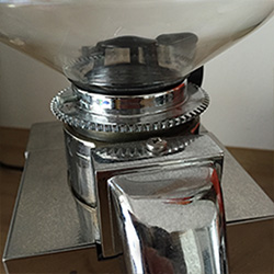
Oh, ah, Alpia. I love it when a plan comes together! The new funnel sits perfectly in the coffee grinder. Let the grinding begin!
i.f.

CD storage for kids with acrylic cover and exchangeable background
We had a plan: Let us organize all those music and audio book CDs with two CD storage car sun visors. Pull them out, push them in, very easy! The reality: Yes, pulling out is easy. But no, putting them back tidily is complicated. Virtually impossible. Ok, no difference to the other stuff that is taken out of boxes, drawers, or shelves and scattered to the four winds. 😉 So let’s face reality: The plan failed!
It’s time for a different storage solution.
Project Description
Take a wooden panel. Put a nice picture on the panel to increase the CAF (children’s acceptance factor) as well as the CF (coolness factor) alongside the SOF (show off factor). Cover the picture with a 2 mm acrylic glass plate. Stick about two dozen CD glue dots made of rigid foam on the acrylic glass to act as CD holders. Hang the CD holder on the wall in the children’s room. Put the CDs on the glue dots. See what happens.
Payload
1 x MDF (medium density fiberboard) panel 1188 x 420 x 3 mm
1 x acrylic glass 1188 x 420 x 2 mm
1 x spray paint, white, silk mat
2 x wooden strip 2400 x 14 x 14 mm (used 3104 mm)
1 x sanding surfacer
8 x 3D printed clamp to hold acryl glass on MDF panel
Wood glue, screws, sanding paper.
Howto
 The picture mentioned in the project description will be made up of four printed DIN A3 sheets. The dimensions of one DIN A3 sheet are 42 x 29,7 cm. Putting four sheets beneath each other results in the target size of the MDF panel being 118,8 x 42 cm. We use The Rasterbator to create a PDF photomaster from the picture I’d like to use. The picture to the right shows the resulting four DIN A3 sheets.
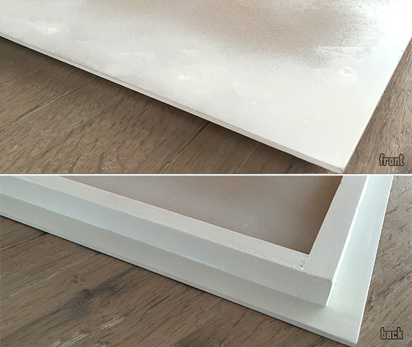
Since the CD holder will have to be mounted somewhere it must not be too heavy. Thus, I decide on a 3 mm MDF panel. Thin as it is, the MDF panel is unstable so I will assemble a frame made of 14 x 14 mm wooden strips on the backside. This frame will a) stabilize the construct and b) allow easier installation of the CD holder to a wall or wardrobe.
Take a look at the 3D drawing to see how the frame is attached to the panel; click the picture to enlarge. I also added the exact dimensioning: Since the wooden strips are 14 x 14 mm I decided to indent the frame 14 mm on each side of the panel. That should give some kind of a floating impressions when the CD holder has been mounted.
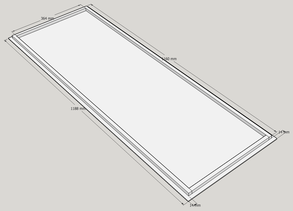
The MDF panel is 118,8 x 42 cm. Thus, we need two wooden strips with a length of 116 cm (118,8-2*1,4) and two with a length of 36,4 cm (42-4*1,4). The four parts are pre-drilled, glued and then screwed together. After that the frame is glued to the backside of the panel and additionally fixed with woodscrews on the front side.
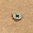 I screwed them in without pre-drilling which was a mistake since the MDF is so dense that I was not able to sink the heads of the woodscrews into the MDF. All
 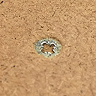 screws looked more or less like the one shown in the picture. Steep learning curve. 😉 The screws must not stick out like this since they are on the front side of the panel where we need a planar surface to attach the DIN A3 sheets. Rework: I let the glue dry, remove the screws, post-drill the holes to a diameter roughly the size of the screw’s heads and, finally, sink the screws into the panel. There you go!
Next step: Use surfacer to fill the screw holes and smoothen the visible parts of the frame for spray painting. After applying the first layer of surfacer it has to dry. Afterwards everything gets sanded. One layer was not enough to get a planar surface on the sunk screws so I applied a second layer of surfacer on the screw holes. Sanding again. Since I did not want to win the 1st prize in a surface sanding and smoothness contest I moved on to spray painting the (visible parts of the) panel with silk mat white spray paint. It was a very good decision to do that in the garden! Spray paint everywhere, especially on the grass surrounding the panel. Would have been an even better idea to wear a dust mask… For a first time sanding and spray painting job the result is quite presentable.
When the paint has dried it’s time to hang the panel on the righthand side of our wardrobe. I consider a couple of possibilities to attach the panel and finally decide on the most direct method: Use four screws to screw that thing to the wardrobe (with pre-drilling the holes). Since the frame did not completely stabilize the MDF panel this is the minimally invasive method I can come up with to have the panel stick to the wardrobe as tight and close as possible. As soon as the panel is mounted and I start to attach the rasterbatorized DIN A3 sheets I realize that it would have been much easier to attach them before the panel was mounted. Too late. I use double-faced adhesive tape, usually used for photo books, to stick the sheets one by one to the panel. Here is what it looks like.

While the 3mm MDF panel was very cheap, just 2,79 € at the local hardware store, I had to search for quiet some time to find a dealer that sells the acrylic glass with dimensions 1188 x 420 x 2 mm for less than 30,- €. Acrylic glass is not that expensive in standard sizes but pre-cutted acrylic parts are, unfortunately, high priced. Now that the acrylic glass had been delivered, how to attach it to the MDF panel? I could drill holes and screw them together. Or I could use glue to tie them together for all eternity. But what if we would like to change the picture? Screwing takes time. Glue sounds to final. I thought that clipping or clamping the MDF and the acrylic panel together should be the best way to go and was, again, scouring the Internet for appropriate parts. After trying the Rapesco Supaclip 40 (too thin, too sharp-edged) and this pretty rare large slide clip (too big) I decided to design and 3D print my own clamps.
After exactly measuring the thickness of the acrylic-glass-paper-MDF-panel stack with a sliding calliper I constructed a clamp using SketchUp. Two test prints later I had ten ideal sized clamps that locked the acrylic glass snugly into position on the MDF panel. Here’s the 3D drawing of the clamp and a picture of 8 of the 10 printed clamps (PLA); click to enlarge the 3D drawing. The STL file is available for download.

We are ready for the final assembly stage: Glue dots and CDs! You will find a lot of offers for 16mm diameter CD glue dots on eBay, e.g., here. They are available in different colors but black and white prevail. It took a bit of thinking and patience to evenly distribute the glue dots over the acrylic glass plate. The CDs should have the same space between each other and to the sides of the panel. Tricky, since the glue dots stick like hell. No chance for trial and error. The result would not pass remeasurement but it’s ok from a distance.

In the picture you can see on the left-hand side the CD holder with attached acrylic glass plate using the clamps. Second to left a couple of glue spots. Second to right 15 attached glue spots and 14 CDs. Rightmost picture: This is it! The finished CD holder with a full cast of 27 CDs. Click picture to see a bigger version of the final result.
Yes, you will not be able to gloat over the nice picture in the background. At least not if the CD holder is full to the brim. But design is about form that follows function. Right? 😉
i.f.

RIBB@TACKING Bruce Lee – a C64 game tribute and homage
One day end of 2015 I stumbled upon some pretty kewl voxel art by Metin Sevin. Amongst many others like Mario Bros, Pacman, or Donkey Kong, I was immediately fascinated by the 3D rendered Bruce Lee Commodore 64 game tribute picture. I contacted Metin and asked him if his work is for sale and he kindly pointed me to society6 where a lot of his art is available in various formats. If you are interested in Metin and his work you can find out more in this interview at the end of this blog post. Due to some other planned projects based on Ikea Ribba frames I had one 23x23cm frame on stock so the 8″x8″ Bruce Lee art print would fit just fine. Shipment from Illinois/USA took about two weeks and I was ready to go for my art project!
tl;dr Watch the video to see what this project is about. Making of with gory details below video.
Project Description
Take the 8″x8″ Bruce Lee art print and put it in a 23x23cm Ikea Ribba frame. Use an Arduino to play the C64 Bruce Lee game title music at 12am and 7pm. Announce every hour starting with the first 3secs of Carl Douglas’ Kung Fu Fighting song and indicate the current hour by an according number of Yamo’s calls (the green Sumo in the game). Announce a quarter past, half past, and a quarter to with the Ninja’s stick strike sound ringing out once, twice, or thrice, respectively. Finally, add a capacative touch sensor to cycle through all Bruce Lee game sounds by touching one corner of the Ribba frame.
Payload
1 x 8″x8″ Bruce Lee art print from society6.
1 x RIBBA frame from Ikea seems no longer to be available. You could use a 25×25 cm Sannahed frame as a replacement.
1 x Visaton K28.40 8Ω, Price comparison idealo
1 x Arduino Nano e.g. from eBay
1 x LM386 Audio Amplifier Module e.g. from eBay
1 x DS3231 Real Time Clock (RTC) e.g. from eBay
1 x CR2032 battery for DS3231 RTC
1 x SD Card Module e.g. from eBay
1 x SD Card 1GB is sufficient
1 x 5V 1A power supply
Cables, solder and iron, hot-melt gun, screws, (cordless) screwdriver, drill, side cutter, etc.
A 1GB SD would have been sufficient since the WAVE files are very small. Unfortunately, I threw away old small capacity SD cards years ago “…when should I ever need a one or two GB SD card again?” Well, now I know the answer. Thus, I had to use an 8 GB SD card.
Audacity will be helpful to recode the Bruce Lee tunes to the required format.
Howto
Order the Bruce Lee voxel from society6. Wait approximately two weeks until it arrives; might heavily depend on where the item is shipped to. 😉 While waiting: a] Buy a 23x23cm RIBBA frame at your local Ikea. b] Prepare the necessary electronics and code to get the thing up and running.
Hardware
For the hardware part: Glue the required components, i.e. Arduino Nano, amplifier, SD card module, DS3231 RTC w/ CR2032 battery to the back of the RIBBA frame. It might look like this.
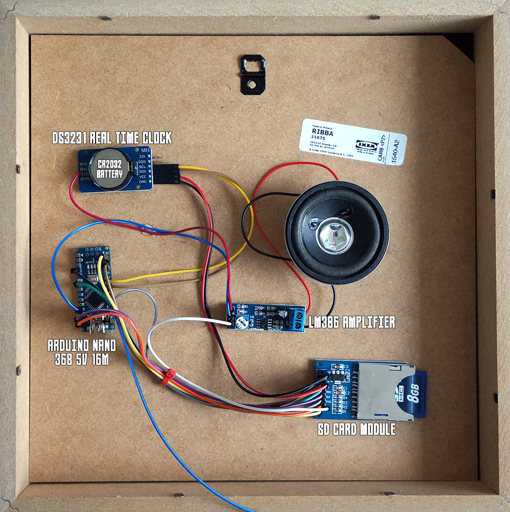
NB: This was my first shot with the loudspeaker directly glued to the backside as can be seen in the photo. My assumption that the – sort of abyssal – RIBBA frame will act as a good resonator
WAS WRONG. When I hung up the picture on the wall for the first time you could barely hear anything. The loudspeaker radiating directly to the wall was nearly completely muted since the sound waves cannot escape the frame.
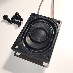 New solution: Drill a plethora of holes into the bottom part of the frame and attach a (smaller) loudspeaker so that its sound waves can go through the holes. There are roughly 3 cm space between the backside (with the components) and the wall-facing side of the frame. Thus, I needed a speaker with a radius of max(3cm). I found an fairly good sounding 2,8x4cm rectangular-shaped speaker from Visaton that would fit snuggly into the available space (cf. picture).
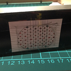 I created a drill template with the speaker’s exact dimensions by laying a piece of paper on top of it and tracing its contours with a pencil. Old school but works! After that I drew a mesh pattern with a lot of drill holes. That could have been the maiden trip for my drill press…but I went with the cordless screwdriver that did a nice job on drilling the 90+ holes. The template was fixed with sticky tape to the frame before drilling. I covered the whole template with tape to avoid frayed drill holes. This worked pretty good on the template
 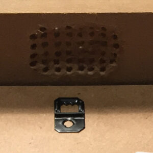 side but not on the inside of the frame. The RIBBA frame is made of chipboard so I lost quiet some material while drilling. You can see in the picture that the inside is not flat anymore but sort of curved due to the lost material. Next time I would apply sticky tape to the inside too.
 The holes needed some afterwork, i.e., burring and removing frayed pieces. The pictures do not show the final stage of afterwork so you will have to trust me that the result was ok. Especially, since the holes are on the bottom side that will, most likely, hardly been seen or looked at when the frame is hanging on the wall. I was happy with the result and moved on to screw the Visaton speaker into the frame with four black and tiny flat-head screws that were giving me a hard screwing time.
This is how the final setup looks like.
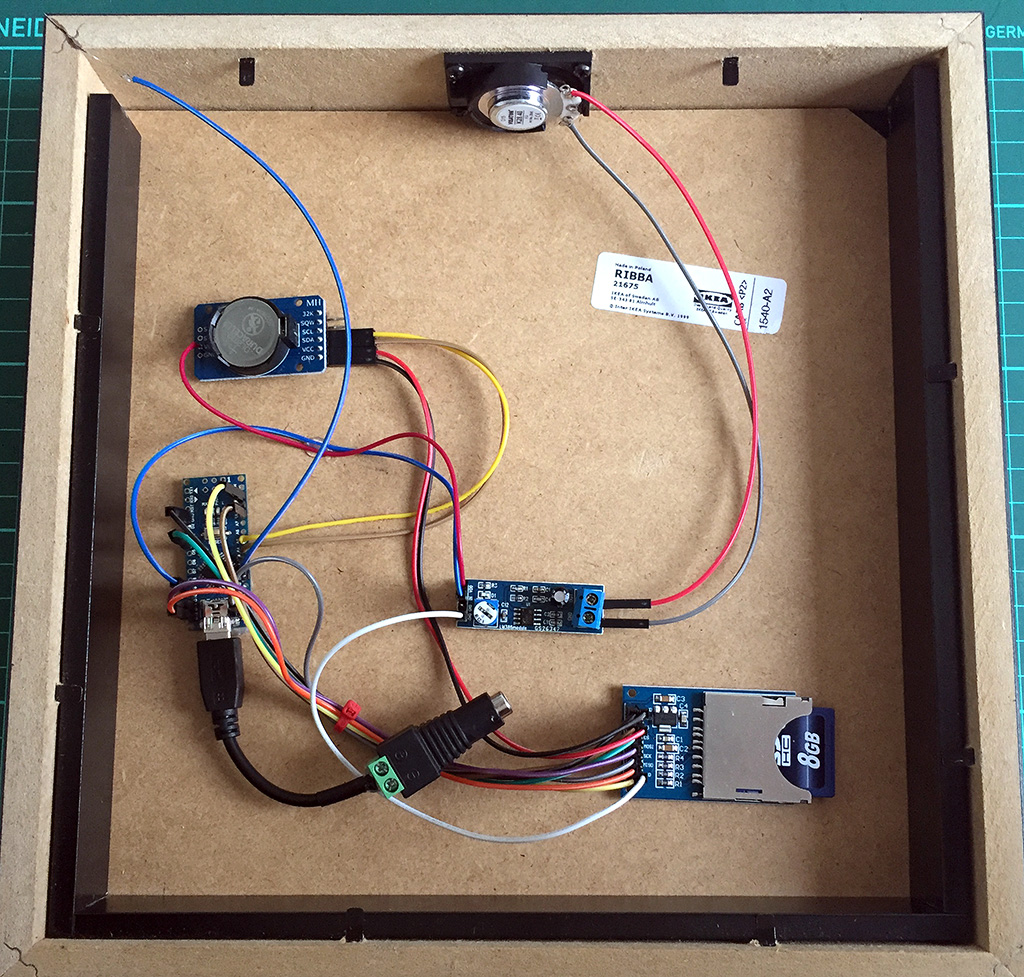
Note the blue cable going to the upper left corner?
This is the capacitive touch sensor wire. 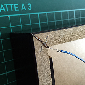 It is basically a piece of zinc coated copper wire bent to a 90° angle and sticked exactly to the corner of the frame using super glue. It was then painted black and soldered to the blue cable to have it connected to the Arduino. With this switch I would later be able to play all Bruce Lee game tunes one after another by repeatedly touching the bottom left corner of the frame. Actually, the ADCTouch-Library used is doing such a great job that the Arduino can react to a finger (or a hand, or some other body part) just coming near to the wire. You can measure changes in the wire’s capacity without even touching it. Awesome!
What’s missing? Yes, details on the wiring. The correct wiring might be hard to find out by just looking at the pictures, not least since my wire color scheme is a bit, eh, inconsistent. So here’s a Fritzing breadboard view of the wiring.
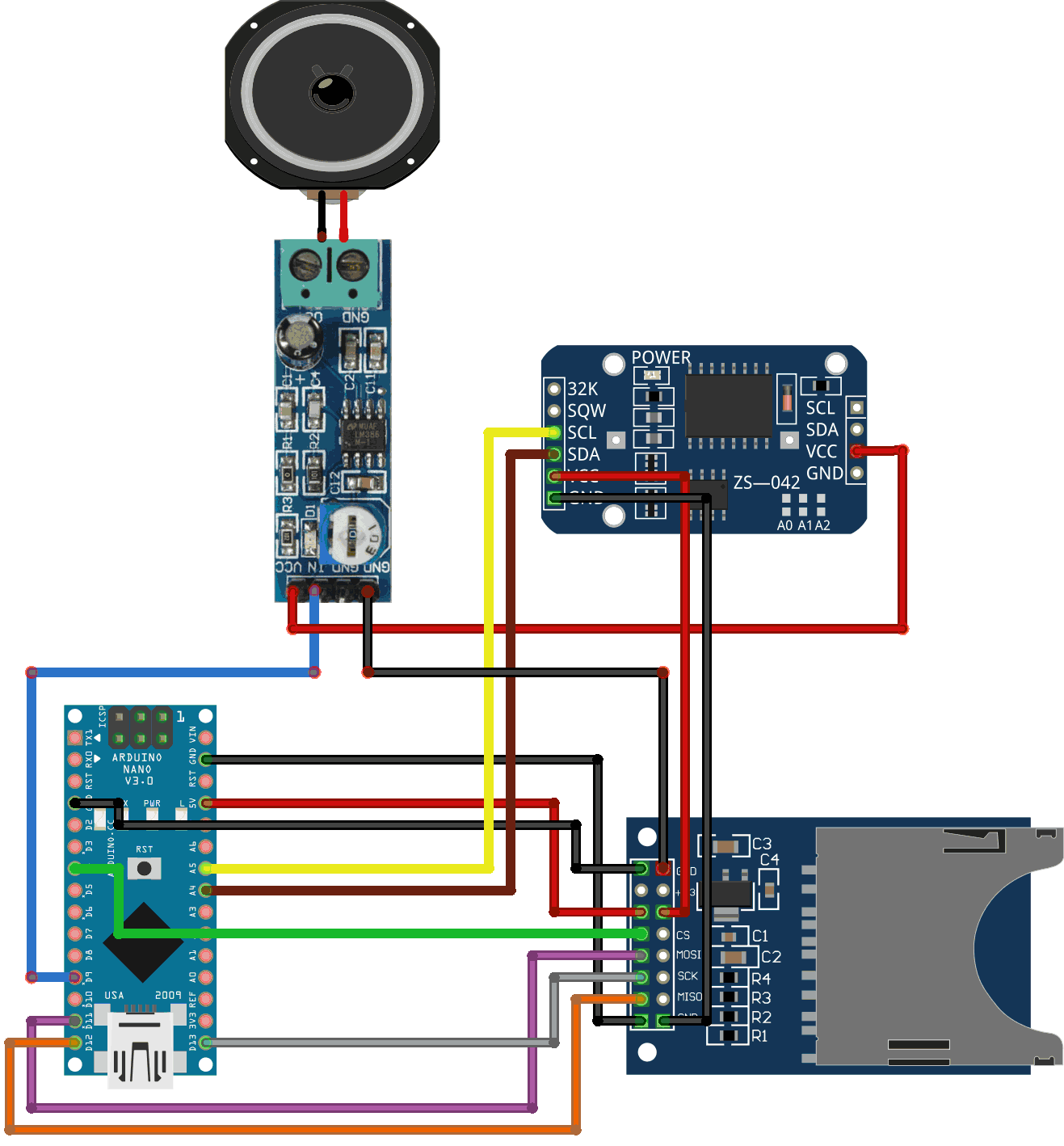
That should cover the most important aspects of the hardware. But all this hardware is nothing without software. Let’s move into the matrix.
Software
Code is poetry
There are more lines of code in the Arduino sketch (GitHub) than needed to implement the behaviour as described in the Project Description. Nonetheless, some of the code is helpful for debugging purposes and some other for fiddling with the TMRpcm Library.
This library is used “for asynchronous playback of PCM/WAV files direct (sic!) from SD card”. The WAVE files must be in a specific format, i.e., 8-bit, 8-32khz Sample Rate, mono. Thus, do not expect Hifi quality! I wrote a separate article WAV-Dateien von SD-Karte mit Arduino abspiele where you will find the gory details about the required file format, how to convert, e.g., an mp3-file using Audacity into this specific WAV-format, how to format the SD card – if required, how the WAV-files have to be named on the SD card (8.3. SFN – short file name from the good ol’ MS-DOS times), and a short Arduino sketch to test the TMRpcm lib.
The ADCTouch library is required for utilizing capacitive touch sensors without any additional hardware.
Debugging with “Serial.print()” is not that funny so we’re using the Streaming library to provide a C++ like << operator that allows constructs like Serial << F( "Current volume is " ) << gVolume << "." << endl; which is very convenient. NB: With the macro F() you put strings in an Arduino's flash memory instead of the sparse static RAM (SRAM) leaving more space for variables and such. The ATmega328 chip found on the Uno has the following memory:
Flash  32k bytes (of which .5k is used for the bootloader)
SRAM   2k bytes
EEPROM 1k byte
Flash is plenty but SRAM isn't - so there is reason to always save SRAM!
Finally, we need the DS3232RTC and Time library to handle the real time clock. Europe will not let go of the daylight saving time (DST) idiocy. Summer time is switched on at the last Sunday in March where 2 o'clock becomes 3 o'clock. Vice versae at the last Sunday in October where 3 o'clock becomes 2 o'clock. We have to recognize the DST so the Bruce Lee cookoo works both in summer and winter. 😉 Thanks to user "jurs" from the German Arduino Forum we have a great European daylight savings time calculation function fIsSummertime() that returns "true" when we're in summer time and false if not.
The Arduino sketch
Sketch also available on GitHub in the RIBBAttacking-Bruce-Lee repository.
Interview with the artist
Metin and I had a nice e-mail-chat while the project was ongoing. There are quiet some analogies in our CVs like being born in the 1970s, growing up with 8-bit computers, adjusting the datassette's azimuth with a screwdriver, hanging out at arcade halls, and - of course - liking minimalistic pixel graphics. Here is short interview with Metin to get you in touch with him as a digital artist and his voxel creations.
Metin, who are you?
My name is Metin Seven, I was born in the 1970s, and grew up in the 1980s with the first 8-bit and 16-bit generations of game consoles and 'home computers', particularly the Atari 2600, CBS ColecoVision, Commodore 64 and Commodore Amiga.
What is your artistic spectrum, i.e., what kind of art do you make/prefer?
I'm a die-hard digital artist. I used to draw on paper as well, but I prefer the flexibility of the digital screen. I started creating pixel art for Amiga demos in the late 1980s. That soon evolved into creating pixel graphics for commercial games, television commercials and children's animation series in the 1990s, all done using software like Deluxe Paint and Personal Paint on an Amiga. Since the late 1990s I've shifted towards 3D graphics creation, but pixel art will always keep a special place in my heart.
Why retro games and what is your reference to this genre?
Ever since I was a little kid I was enchanted by the magic glow of the digital screen. I used to hang out at arcade halls, playing the first 8-bit games, such as Donkey Kong, Lady Bug, Pac-Man and Pengo. When I was not playing them myself, I could stare at people playing the games for hours. The first pixel graphics had this pure, iconic quality because of the low resolution restrictions for sprites and such. It's great to see that atmosphere return in the current wave of minimalistic pixel art games for mobile devices.
Did you have decent experiences with the C64?
Definitely. During my school days I spent just about every afternoon and evening playing Commodore 64 games, first loading them using the Datassette tape recorder, adjusting the azimuth when necessary. After a while I bought a floppy disk drive. LOAD "*",8,1 😀
How did you come to create voxel pictures? Where does the idea come from?
During the 2000s I created a lot of stylized 3D illustrations for printed magazines and newspapers. My use of shapes and colors reflected my game pixel art background, and gradually my illustration style became more elementary, until I arrived at a point that fully made sense — a blend between pixel art and 3D artwork: voxels. It was then that I decided to start paying tributes to my childhood love: 8-bit and 16-bit games.
Can you tell us something about the voxel creation process?
My first voxel images were created in 3ds Max in the mid-2000s, extruding blocks of quadrangular polygons. That was quite a hassle, and I was eager to find a dedicated voxel editor. I found that in the shape of Paint3D for Windows. I got in touch with the coder and suggested a number of features, which he kindly implemented.
When I switched to Mac OS X in 2014, I started using Qubicle, also a versatile voxel editor. I guess MagicaVoxel would be the tool of my choice today, but to be honest I've become a bit saturated when it comes to voxel creation, although there’s a good chance I'll return to it some day.
Where should we go if we'd be interested in more from you?
The best starting place is my portfolio site metinseven.com, there you will find links to my online shops, offering 3D prints, 2D art prints, stock 3D models and stock illustrations.
Many thanks for this interview, and my sincere compliments to you regarding your clock creation based on my voxel tribute to the classic 8-bit Bruce Lee game.
The pleasure was all mine! Keep on the good work!

i.f.

WAV-Dateien von SD-Karte mit Arduino abspielen
 Eins gleich vorweg: Hifi-Qualität darf man von der hier beschriebenen Lösung nicht erwarten. Aber als Low-Budget-Player für einfache Zwecke reicht es auf jeden Fall. Habe ich beispielsweise hier im Kunstprojekt RIBB@TACKING Bruce Lee – a C64 game tribute and homage verwendet.
Was man braucht
Natürlich einen Arduino; der hier beschriebene Aufbau wurde mit einem Uno getestet. Alle 328er basierten, also auch Nano, LilyPad, Pro etc. sollten gleichermaßen funktionieren.
Da die WAVE-Dateien irgendwo abgespeichert sein müssen, bietet sich ein SD Kartenleser an. Es gibt Breakout Boards mit Micro-SD-Karten Slot oder andere Shields, auf denen solch ein Slot bereits integriert ist, bspw. das Ethernet-Shield. Hier kommt ein sehr einfacher 1 EUR SD-Kartenleser von eBay zum Einsatz. Dazu eine (alte) SD Karte.
Damit man etwas hört, braucht es einen Verstärker. Bryan beschreibt in diesem Blog-Artikel, wie man mit einem einzigen Transistor nebst Widerstand (4,7 kOhm) einen simplen Verstärker zusammenschustert. Der BC548B hat nicht ausreichend verstärkt. Mit dem 2N3904 (eBay) macht es mehr Spaß.
Dazu natürlich ein Lautsprecher, da hatte ich noch einen mit 0,25 Watt 4 Ohm auf Halde liegen.
Verkabelung / Aufbau
Die Anbindung des SD-Kartenlesers erfolgt über die Hardware SPI Pins des Arduino. Welche Pins das genau sind, hängt vom Arduino-Typ ab. Die hier gezeigte Verkabelung sollte für alle 328er Typen (Nano, Uno, etc.) funktionieren. Chip Select ist frei wählbar; vgl. auch der weiter unten stehende Arduino Sketch. Die Schaltung auf dem Breadboard ist der erwähnte Ein-Transistor-Verstärker. Wenn man hier den Widerstand zwischen Arduino-Ausgang (Pin 9) und der Transistorbasis zu klein wählt, kann man nach kurzer Zeit auf dem Transistor Eier braten, da zu viel Strom durch die Collector-Emitter-Strecke fliesst.

Wagemutige können den Widerstand einfach mal ganz weglassen und sich an einer, dann, recht ordentlichen Beschallung nebst Transistorheizung erfreuen. Das sei hiermit also ausdrücklich nicht empfohlen.
| Kartenleser PIN | Arduino PIN | Was ist das? |
|---|---|---|
| GND | GND | Ground |
| +5V | 5V | Volle Power! 🙂 |
| MOSI | 11 | DATA, MOSI DATA, SDA, Hardware MOSI |
| MISO | 12 | MISO, Hardware MISO |
| CLK | 13 | CLK, SCL, Hardware SCK |
| CS | 4 | CS, Chip Select |
| GND | GND | Ground |
In der Tabelle ist die PIN-Verkabelung noch einmal aufgeführt. Der verwendete SD-Kartenleser hat zwei GND-Anschlüsse und funktioniert auch nur zuverlässig, wenn tatsächlich beide mit Masse verbunden werden. Der Lautsprecherausgang ist, ebenso wie Chip Select, über den Arduino Sketch frei wählbar (hier PIN 9).
Zwei Blog Posts haben bei Verkabelung und Inbetriebnahme gut geholfen. Zum einen dieser Beitrag bei maxoffsky.com sowie insbesondere diese Anleitung auf instructables.com.
Format der SD Karte
Die verwendete SD-Library unterstützt prinzipiell die Dateisysteme FAT16 und FAT32. Es wird jedoch empfohlen, wenn möglich, FAT16 einzusetzen. Bei mir hat’s mit einer FAT32-formatierten SD-Karte nicht funktioniert, daher wollte ich sie “mal eben” auf FAT16 formatieren. Das geht auch mit MacOS Bordmitteln, ist aber etwas komplizierter, als erwartet. Dieser Post im Adafruit-Forum beschreibt den Weg in Englisch; hier in knappem Deutsch:
- SD-Karte in den Mac stecken.
- Terminal-Fenster öffnen. Bspw. mit CMD+Space, dort “terminal” tippen und Return.
- Geräte-ID finden. Dazu im Terminal
dfgefolgt von Return eingeben. Es erscheint eine Filesystem-Übersicht, die unter anderem die folgenden Informationen enthält. Ganz unten ist die SD-Karte “NO NAME” zu sehen. Wer auf Nummer sicher gehen will, gibt seiner Karte einen eindeutigen Namen. Dann kann man sie in dieser Übersicht schneller finden. Die in den folgenden Schritten benötigte Geräte-ID lautet/dev/disk3s1.Filesystem Used Available Capacity iused ifree %iused Mounted on /dev/disk1 909007896 65197032 94% 113689985 8149629 93% / devfs 371 0 100% 642 0 100% /dev map -hosts 0 0 100% 0 0 100% /net map auto_home 0 0 100% 0 0 100% /home /dev/disk3s1 20928 4172608 1% 512 0 100% /Volumes/NO NAME
- SD-Karte unmounten (nicht auswerfen!). Im Terminal
diskutil unmount /dev/disk3s1gefolgt von Return eingeben. Dabei disk3s1 natürlich durch die eigene Geräte-ID ersetzen. Erfolgreiches unmounten wird bspw. mitVolume NO NAME on disk3s1 unmountedquittiert. - FAT16 Filesystem auf SD-Karte schreiben. ACHTUNG! Der folgende Befehl löscht alle Daten auf dem Gerät. Wenn die Geräte-ID nicht die von der eingesteckten SD-Karte ist, sondern bspw. aus Versehen die der eingebauten Festplatte, dann wird diese gelöscht. U have been warned.
Folgendes Kommando im Terminal eingeben und nicht vergessen die Geräte-ID anzupassen.newfs_msdos -F 16 /dev/disk3s1
Ich habe alle Warnmeldungen, die der Befehl produziert hat, konsequent ignoriert und als Lohn der Mühe im Anschluß eine lauffähige FAT16-formatierte SD-Karte gehabt.
Format der WAVE Dateien
Die Library TMRpcm benötigt zum Abspielen die WAVE-Dateien im Format acht Bit, acht bis 32 kHz Sample Rate, mono. Im WIKI zur Library werden zwei Wege beschrieben, wie man iTunes oder Audacity verwenden kann, um aus dem musikalischen Quellmaterial das Zielformat zu generieren. Audacity ist prima, und so geht’s damit:
- Hauptmenü “Tracks”, dort “Stereo Track to Mono” wählen.
- Unten links die “Project Rate (Hz)” mit dem Popup auf 8000, 11025, 16000, 22050 oder 32000 setzen. Je niedriger die Sampling Rate, desto schlechter die Qualität.
- Hauptmenü “File”, dort “Export Audio…” und im File Selection Dialog unten als Format “Other uncompressed files” wählen. Dann “Options…” klicken und als Header “WAV (Microsoft)” sowie bei Encoding “Unsigned 8-bit PCM” wählen. OK.
- Datei mit “Save” speichern.
Dateinamen
Dateinamen müssen zwingend dem – aus alten MS-DOS Zeiten bekannten – 8.3-Format folgen, also maximal acht Zeichen für den Dateinamen gefolgt von Punkt und einer Endung mit drei Zeichen beispielsweise “NAME0001.EXT”. Der Dateiname kann kürzer als acht Zeichen sein, in keinem Fall aber länger. Die Wikipedia widmet dem 8.3 short filename (SFN) tatsächlich einen eigenen Artikel.
Arduino Sketch
Der folgende Sketch bindet zunächst die benötigten Libraries ein, definiert Chip Select- und Lautsprecherausgangs-PIN, initialisiert die SD-Karte mit SD.begin() und spielt im Erfolgsfall die Wave-Datei snakec16.wav direkt von der SD-Karte ab. Im Fehlerfall wird eine kurze Meldung über den seriellen Monitor ausgegeben.
#include
#include
#include
#define CHIP_SELECT_PIN  4
#define SPEAKER_PIN      9
TMRpcm tmrpcm;

void setup( ) {
  tmrpcm.speakerPin = SPEAKER_PIN;
  Serial.begin( 9600 );
  while ( !Serial ) /*mt*/ ;
  if ( !SD.begin( CHIP_SELECT_PIN ) )
    Serial.println( "SD fail" );
  else {
    tmrpcm.play( "snakec16.wav" );
    delay( 5 );
  }
}

void loop( ) {
}
Wenn alles läuft…
…dann sollte das in etwa so aussehen, wie in dem Video.
OLED 0,96″ Zoll Display an den Arduino anschließen
Bei eBay, Aliexpress & Co. gibt es zahnlose Mini-OLED-Displays, beispielsweise für den Betrieb an einem Arduino. Dabei sind die gängigen Größen 0,96 Zoll und 1,3 Zoll mit Auflösungen von 128 x 64 oder 128 x 32 Pixeln. Die Displays sind selbstleuchtend und werden in weiß, blau, gelb, Kombinationen davon oder auch “full color” angeboten. Die Full Color Displays stellen dann üblicherweise 65K Farben dar.
Es werden unterschiedliche Kommunikationsprotokolle unterstützt, in der Regel entweder I2C oder SPI oder beides. Dazu kommen unterschiedliche Driver Chips, für die die richtige Library benötigt wird, um das OLED ansteuern zu können. Gängig und gut unterstützt ist der Driver Chip SSD1306, der u.a. mit den folgenden beiden Libraries angesteuert werden kann: Adafruit_SSD1306 (github) oder U8glib (github). Wer ein OLED mit SS1106 Driver Chip erwischt hat, kann es mit der SH1106_SPI Library (github) versuchen.
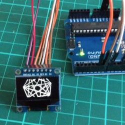
Dieser Post zeigt den Anschluß und Betrieb eines einfachen, weißen 0,96″ Zoll OLED Displays (eBay) mit SSD1306 Driver Chip und sieben Anschluss-Pins an einen Arduino Uno. Nano, und alle weiteren Modelle mit ATmega328 Pinout, dürften auf dieselbe Weise angesteuert werden können. Im Zweifel das Datenblatt des Arduinos zu Rate ziehen.
Im folgenden Video ist das OLED im Einsatz zu sehen. Die Chord-Animation ist von Hari Wiguna, sein Kode steht auf GitHub bereit.
Um ein OLED erfolgreich ansteuern zu können, ist die richtige Verdrahtung zwischen Arduino und Display wichtig. Dabei wird es durch die Tatsache, dass die Displays mit unterschiedlicher Anzahl und Beschriftung der Pins geliefert werden nicht einfacher. Die Libraries erlauben üblicherweise die Verwendung von Software oder Hardware SPI, wobei letztere Variante deutlich schneller ist. Hardware SPI erfordert mehr Anschluss-Pins als Software SPI.
| OLED Anschluss | Arduino PIN | Was ist das? |
|---|---|---|
| GND | GND | Ground |
| VCC | 5V | Volle Power! 🙂 |
| D0 | 13 | CLK, SCL, Hardware SCK |
| D1 | 11 | DATA, MOSI DATA, SDA, Hardware MOSI |
| DC | 6 | Data/Command |
| DS | 7 | CS, Chip Select |
| RES | 8 | Reset |
Das im Video gezeigte 0,96″ Display ist zur Ansteuerung durch Hardware SPI entsprechend der Tabelle mit dem Arduino zu verbinden. Bitte unbedingt prüfen, ob das eigene Display für 5V ausgelegt ist! Im Zweifel am 3,3V Pin anschließen und erst einmal damit versuchen. Die “Was ist das?”-Spalte in der Tabelle zeigt die ausgeschriebenen, gängigen oder alternativen Bezeichnungen der Anschlüsse; vielleicht hilft es dem einen oder anderen bei der Verkabelung. Ich fand diesen Beitrag von paulwb im Adafruit-Forum sehr hilfreich, um das Display nach einigen erfolglosen Versuchen endlich zum Laufen zu bringen.
Hier noch der Arduino-Sketch zur Darstellung der Animation wie im Video.
#include
#include
#include
#include

/* Wiring for Hardware SPI
    GND ------- ground
    VCC ------- 5V
    D0 -------- 13 hardware SCK
    D1 -------- 11 to hardware MOSI
    DC -------- 6 (user choice, defined below)
    DS -------- 7 (user choice, defined below)
    RST ------- 8 (user choice, defined below)
  Hardware MISO (12) unused */

#define OLED_DC     6
#define OLED_CS     7
#define OLED_RESET  8
Adafruit_SSD1306 display( OLED_DC, OLED_RESET, OLED_CS );

void setup( ) {
  display.begin( );
  display.clearDisplay( );
  display.display( );
}

int nFrames = 36;
void loop() {
  for ( int frame = 0; frame < nFrames; frame++ )
    HariChord( frame );
  for ( int frame = ( nFrames - 1 ); frame >= 0; frame-- )
    HariChord( frame );
}

void HariChord( int frame ) {
  display.clearDisplay( );
  int   n   = 7;
  int   r   = frame * 64 / nFrames;
  float rot = frame * 2 * PI / nFrames;
  for ( int i = 0; i < ( n - 1 ); i++ ) {
    float a  = rot + i * 2 * PI / n;
    int   x1 = 64 + cos( a ) * r;
    int   y1 = 32 + sin( a ) * r;
    for ( int j = i + 1; j < n; j++ ) {
      a  = rot + j * 2 * PI / n;
      int x2 = 64 + cos( a ) * r;
      int y2 = 32 + sin( a ) * r;
      display.drawLine( x1, y1, x2, y2, WHITE );
    }
  }
  display.display( );
}

Schwergängige Schubladen beim Helmer Schrank von Ikea
Aktuell ist das HELMER Schubladenelement in weiß, grau, grün und rot erhältlich. Das gab es auch mal in orange und beige, but times change. Die beige-farbene bzw. weiße Variante ist mit einem Lack überzogen, der – im Gegensatz zu den anderen Farben – etwas rauh wirkt. Dadurch gleiten die Schubladen auf ihren Schienen deutlich schlechter, als dies bei der orange-farbenen, grünen und roten Version der Fall ist. Schubladen und Führungsschienen scheinen aufgrund der Lack-Struktur aneinander “hängen” zu bleiben. Das nervt schon gewaltig, da das Schubladenelement auf Rollen steht und so beim Öffenen und Schließen der Schubladen der ganze Schrank mit verschoben wird.
But fear you not, for thy emperor is here! Es gibt eine geradezu genial einfache Lösung und die heißt Silikon-Öl. Nicht Spray, sondern Öl. Warnung an dieser Stelle: Auf keinen Fall Silikon-Spray in der Wohnung verwenden – das landet überall und macht insbesondere den Boden zu einer sehr, sehr gefährlichen Rutschfalle! Zurück zum Öl. Das gibt es in den unterschiedlichsten Viskositäten und nach kurzer Recherche habe ich zumindest so viel verstanden, dass – mit meinen Worten gesagt – die Größe der Viskositätszähl die “Zähflüssigkeit” des Öls beschreibt. Daraufhin habe ich mich für dieses WS Silikonöl mit einer Viskosität von V=12500 entschieden. Das ist sehr dickflüssig und lässt sich daher sehr einfach mit einem Finger auftragen.
Das Vorgehen: Schublade raus, linke und rechte Führungsschiene mit dem Silikonöl einschmieren, Schublade wieder rein. Back’n’forth, back’n’forth. Gleitet, wie auf Kugellagern!
Günstiger Schubladeneinsatz mit Ikea Teppichgleitschutz STOPP
 Die Ikea Schubladen-Matte VARIERA, Artikelnummer 800.128.53, ist robust und leistet mit ihrer leicht genoppten Oberfläche, was sie soll: Den Schubladeninhalt davon abhalten in der Schublade hin- und herzufliegen. Die Matte ist 150 x 50 cm groß und kostet 3,99 EUR. Ich habe die Matte für die etwa 37,5 x 23,4 cm (Innenmaß) Fächer eines Helmer-Schranks verwendet. Eine Matte sollte für alle sechs Fächer reichen, nur das Zuschneiden ist etwas mühselig, da die Matte recht dick ist. Dadurch ist Variera wiederum sehr robust, geradezu unkaputtbar. Was also könnte gegen die Matte sprechen?
 Kurze Antwort: Wenig! Aber wenn man nichts suchend – ausser natürlich Servietten – durch Ikea streift, dann kann man in der Teppichabteilung den Teppichgleitschutz STOPP finden. Und damit einen Ikea-Hack aus der Kategorie “Sparfuchs” landen, denn mit kleinen Abstrichen bei der Optik lässt sich STOPP auch als Schubladengleitschutz einsetzen. Besagter Teppichgleitschutz STOPP, Artikelnummer 802.278.77, kostet ebenfalls 3,99 EUR ist aber satte 200 x 67,5 cm groß. Damit lassen sich gleich 13 Fächereinlagen in Helmer-Größe herstellen; reicht also für zwei Helmer-Schubladenelemente mit á sechs Schubladen plus Reserveeinlage. Der Hammer!
Und wem die Schubladen des weißen Helmer-Schranks zu hakelig sind, der findet im Artikel Schwergängige Schubladen beim Ikea Helmer Schrank eine Lösung, um diese mal so richtig schön gleiten zu lassen.

Selbstbauschrank für die Heimtechnik mit Schloß und Lüfter
Auf die übliche Heimtechnik mag kaum ein Haushalt verzichten. Aber wenn sich erst einmal WLAN Router, DECT Basisstation, Hue Bridge, Ethernet Switch und weitere Geräte zusammen mit Netzteilen, Cat5- und USB-Kabeln sowie den unvermeidlichen Mehrfachsteckdosen an einem Ort knubbeln, dann gibt es in der Regel Kräfte, die aktiv gegen derlei Elektronik- und Kabelhaufen arbeiten; vgl. hierzu die Ausführungen zum Wife Acceptance Factor (WAF) in der Wikipedia. Der Gerätepark muß also weg und als einfachste Lösung bietet sich ein Schränkchen an, dass unter einer bereits vorhandenen Tischplatte montiert wird.
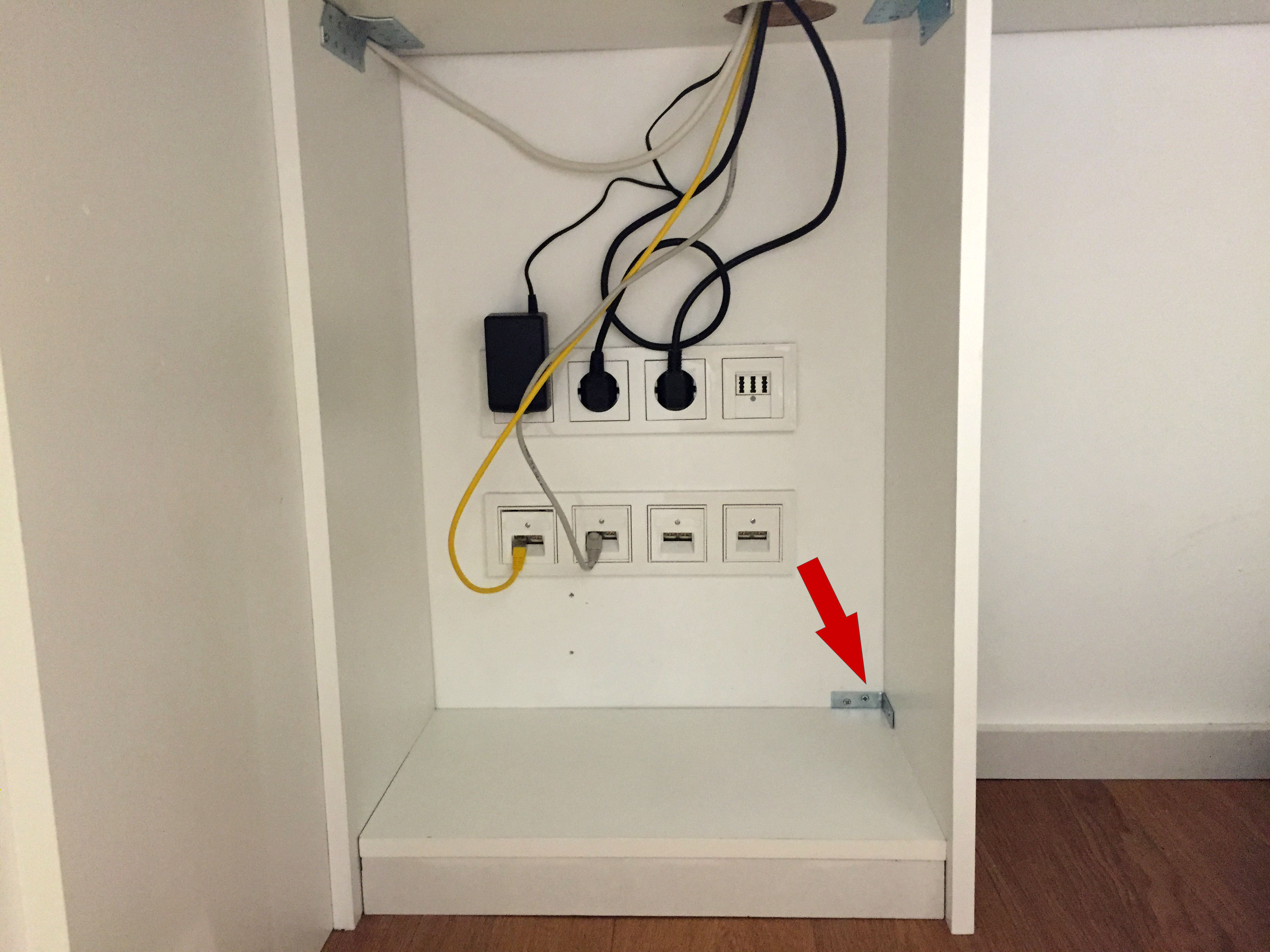
 Der designierte Montageort für den Schrank macht klare Vorgaben zu Breite, Höhe und Tiefe, um möglichst dezent in der Ecke zu verschwinden; vgl. Bild. Das Schränkchen soll in der Höhe vom Boden bis zur Tischplatte reichen, nicht tiefer als 30cm sein und in der Breite die Steck- und Ethernetdosen vollständig abdecken. Ein (fast) exakt passendes Schränkchen war weder im stationären Handel noch Online erhältlich. Maßschreinerei kam angesichts des eher niedrigen Anspruchs an Güte und Verarbeitungsqualität aus Kostengründen nicht in Frage. Fazit: Dann wird das Schränk’sche halt selber gebaut!
Los geht’s mit einer Bierdeckel-Skizze. Der Schrank soll aus 1 cm dicken, weiß laminierten Spanplatten aufgebaut werden. Dazu werden zwei Seitenteile, eine Bodenplatte, eine Leiste und eine Frontplatte für die innenliegende Tür benötigt. Mangels Erfahrung mit Holzarbeiten, wird alles zig Mal durchgemessen, nachgerechnet und kontrolliert.
| Steckbrief “Schrank für Heimtechnik” | ||
|---|---|---|
| Zeitaufwand | 08h 22min 14sek | |
| Material | Holz, Umleimer, Schrauben, Kleber, Aufschraubscharniere, Sparrenpfettenanker | Baumarkt |
| Aufschraubsschloß | Amazon | |
| Temperaturschalter | eBay | |
| Lego Baustein | Sohn 🙂 | |
| Noiseblocker XL2 Rev3 | Google Shopping | |
| Lautsprecherabdeckung | Conrad | |
| Skills | Holzarbeiten, Elektronik | |
| Werkzeug | jap. Zugsäge, Schraubendreher, Akkuschrauber, Dremel, Bügeleisen, Cutter Messer, Schmiergelpapier |
|
Im Baumarkt. Vor Ort stelle ich fest, dass 1 cm dicke Spanplatten gar nicht dick, sondern eher dünn sind. Also spontan vor Ort für 1,6 cm dicke Platten entschieden. Dann stimmen aber meine Berechnungen nicht mehr! Also kurz am Tresen des Holzzuschnitts die Maße nachkalkuliert und die Platten in Auftrag gegeben. Als die Platten fertig sind, stelle ich fest, dass – natürlich – einige Seiten nicht laminiert sind. Brauche ich also noch Umleimer zum Aufbügeln. Den gibt’s aber nicht in 16mm Breite, sondern nur 20mm. Ob sich das später mit dem Cutter-Messer sauber abtrennen lässt…?
Zuhause alle Platten grob aneinander angehalten und festgestellt, dass die “mal eben Nachkalkulation” am Tresen fehlgeschlagen ist: Die Bodenplatte ist um einige Millimeter zu lang. Umpf. Die Platte muß auf jeden Fall gekürzt werden, und zwar ohne passendes Werkzeug. Ich murkse mit der japanischen Zugsäge rum, bis die Platte die richtige Länge hat. Eine gerade Schnittkante sieht allerdings anders aus.
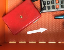
Der Zusammenbau beginnt mit dem linken Seitenteil. Da der Schrank bündig mit der Wand abschließen soll, wird mit der Zugsäge ein rechtwinkliger Teil ausgespart, damit sich das Seitenteil über die Sockelleiste schieben lässt (Pfeil unten rechts). Für das starre Koaxialkabel, oben links im Bild, muss am Seitenteil ein Kanal geschaffen werden, der vorne gerade eben das Kabel durchlässt und weiter hinten etwas mehr Raum bietet. Auch das erledigt die Zugsäge.

Im Anschluß wird die Vorderkante laminiert, was laut Anleitung recht einfach aussieht, sich dann bei der konkreten Umsetzung aber schwerer als erwartet herausstellt. Das Laminierband wird auf die Spanplattenkante aufgelegt und dann mit einem zwischengelegten Handtuch aufgebügelt. Danach schneidet man mit einem Cutter Messer oder passendem Spezialwerkzeug das überstehende Laminatband ab. Wer das kann, ist jetzt wahrscheinlich fertig. Ich musste noch munter mit Schmirgelpapier nacharbeiten, damit eine saubere Kante entsteht. Am Ende sieht’s aber gut aus und das Seitenteil wird mit einem zweckentfremdeten Sparrenverbinder, genauer, einem Sparrenpfettenanker, befestigt.

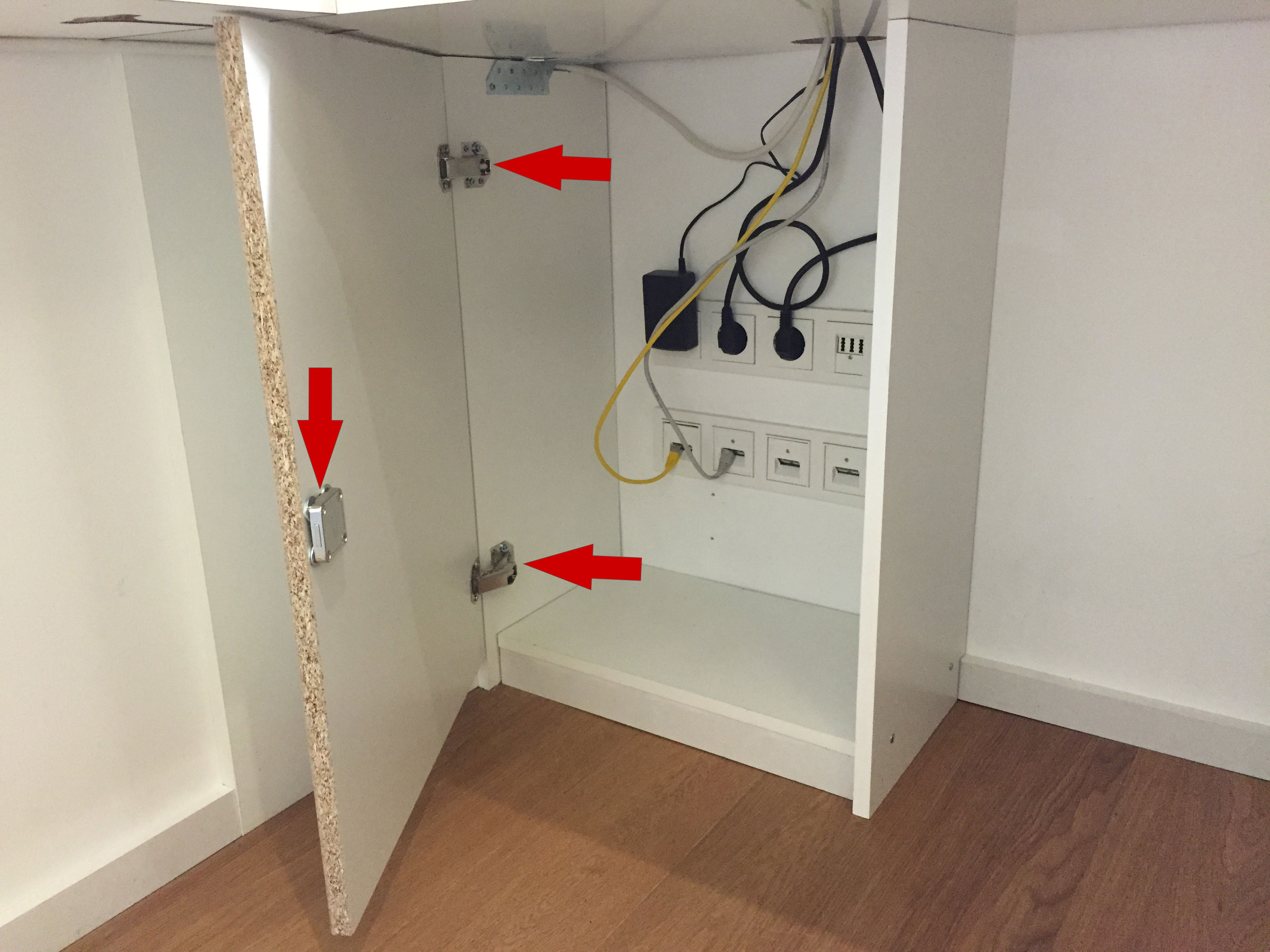
Analog wird mit dem rechten Seitenteil verfahren. Im folgenden Bild ist es bereits “free floating” an der Tischplatte verschraubt; die Fixierung erfolgt im nächsten Schritt beim Einbau der Bodenplatte.

Die Kante der Bodenplatte wird laminiert und im Anschluß der kleine Sockel vorne mit einem Abstand von 8mm zur Kante angeklebt. Weil sich die Bodenplatte am linken Seitenteil nicht mehr festschrauben lässt, wird sie kurzerhand auch hier festgeklebt. Sekundenkleber ist dein bester Freund! 🙂 Hinten liegt die Bodenplatte auf der wandseitigen Sockelleiste auf und wird nicht verklebt. Der Schrank soll sich ja später noch weitestgehend rückstandsfrei entfernen lassen. Abschließend verbinden zwei Schrauben das rechte Seitenteil mit der Bodenplatte. Damit bekommt die Konstruktion bereits eine passable Stabilität.

Die Stabilität reicht aber noch nicht, da die Konstruktion in der vertikalen Richtung – also von der Wand Richtung Vorderseite – beweglich ist. Mit einem kleinen Winkel wird die Bodenplatte mit der Wand verschraubt. Das hält.
Nun zur Tür. Um mich nicht mit Topfbohrungen und der Anschaffung guter, und damit kostspieliger, Forstnerbohrer rumärgern zu müssen, soll es eine innenliegende Tür werden, die mit zwei 90° Feder-Aufschraubscharnieren befestigt wird. Dazu gibt es, bspw. bei Hettich, eine Montageanleitung, die vom ungeübten Holzwurm aber erst einmal verstanden werden will. Und dann basiert diese auf der (Standard?)Dicke von 19mm Möbelbrettern, so daß hier auch noch auf 16 mm umgedacht werden muß.
Vor Befestigung der Tür schien es sinnvoll, zunächst das Zylinderschloß zu montieren. Dazu Abstände vermessen, dann ein Loch mit passendem Durchmesser bohren und das Schloss durchstecken und mit einigen Abstandsscheiben an der Tür festschrauben. Im Bild ist die fertig montierte Tür mit Aufschraubscharnieren und Schloss zu sehen.
Auf zum nächsten, lustigen Teil. Das Schloss hat einen Bolzen, der durch Drehen des Schlüssels ein- und ausgefahren wird. Der ausgefahrene Bolzen benötigt im rechten Seitenteil eine
Vertiefung, in die er einfahren kann,  damit die Tür auch tatsächlich verschlossen ist. Ich bohre mehrere kleine Löcher neben- und untereinander in das Seitenteil, um eine Nut zu erzeugen. Dann wird mit dem Cutter Messer grobschlächtig nachgearbeitet bis ein entkernter kleiner Lego-Baustein (ein “Zweier”) in die Vertiefung passt. Theoretisch hätte es auch beim Bolzen-direkt-in-Spanplatte bleiben können; die Spanplatte schien einen ausreichenden Halt zu gewährleisten. Aber bei dem Schränkchen wurde schon genug gestümpert, dann soll der Bolzen wenigstens ein stabiles Gegenstück erhalten! Nachdem der Lego-Baustein mit Heißkleber (könnte auch Holzleim gewesen sein) in der Vertiefung fixiert wurde, korrigiere ich farbliche Aberrationen zwischen Schrank, Kleber und Lego-Baustein mit einem Emaille-Reparaturstift. Hauptsache weiß. Und ja, schön ist anders.
Tada! Der Schrank mit geschlossener Tür. Etwaige Kommentare zu Spaltmaßen & Co. bitte direkt nach /dev/null.

Jetzt wird die ganze Haustechnik verstaut: WLAN Router, Ethernet Switch, TimeCapsule, DECT Basisstation, Kabelmodem und – nicht sichtbar – die Basisstation des Little Printers (leider End-of-Life), USB Festplatte und zwei Mehrfachsteckdosen nebst fünf Netzteilen. FTW!
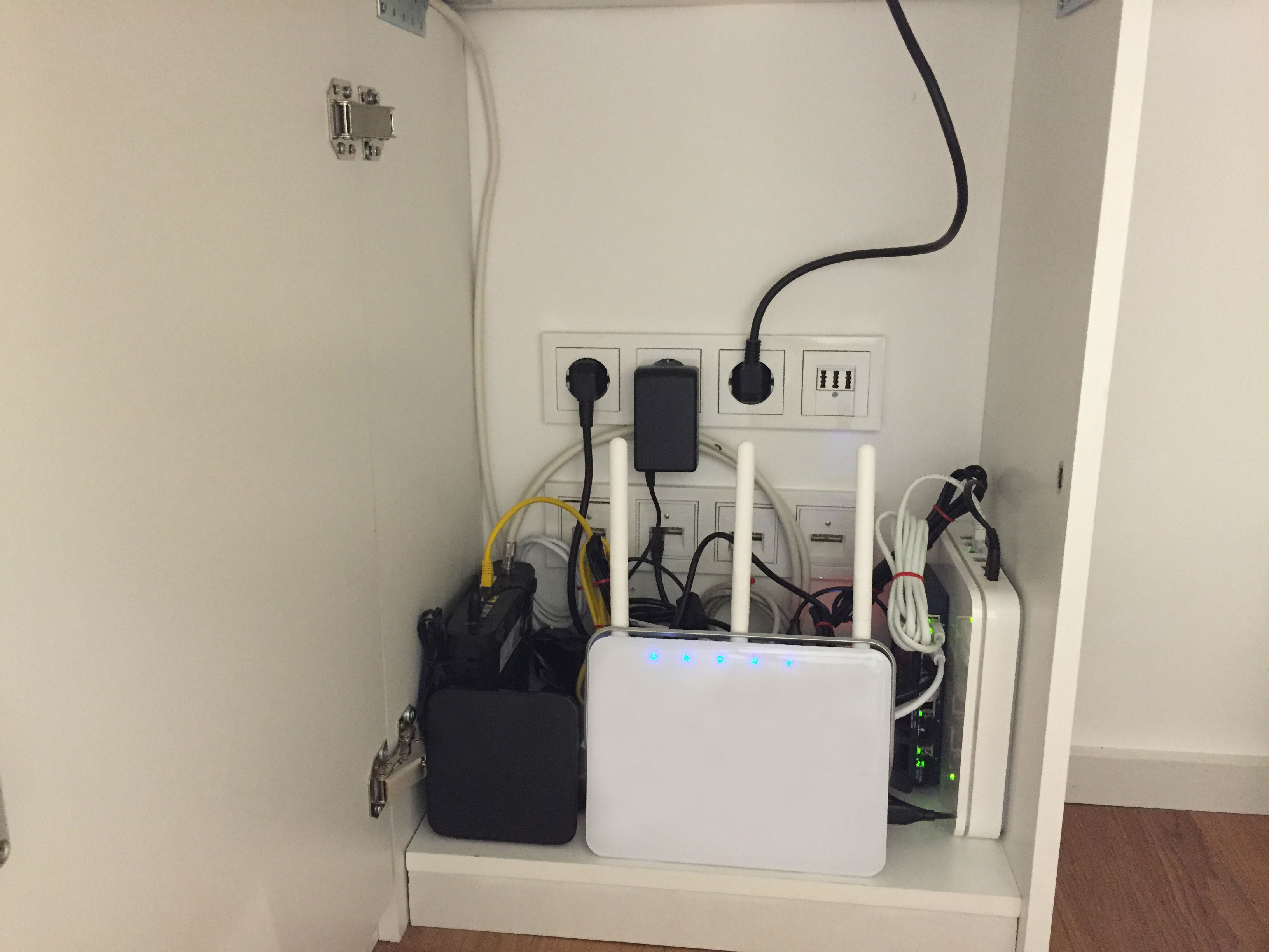
Der Schrank wird wegen Überfüllung geschlossen und ich zitiere Schiller: Von der Stirne heiss, rinnen muß der Schweiß, soll das Werk den Meister loben, doch der Segen kommt von oben. Der Schrank ist fertig. ipse fecit.
Aber so endet die Geschichte nicht.
Nach einigen Verkabelungsoptimierungen fällt mir auf, dass die Gerätschaften im Schrank eines ganz besonders gut können: Strom in Wärme umwandeln. Im Schrank wird es so warm, dass ich mir über Energy Harvesting Gedanken mache. Da habe ich jetzt einen tollen Schrank, aber was, wenn die Elektronik wegen Überhitzung frühzeitig den Geist aufgibt? Kreisch! Ein Kühlsystem muß her. Wasserkühlung nein. Thermoelektrische Kühlung nein. Also Luftkühlung. Neuer Payload: [a] Ein leiser Lüfter, [b] ein Temperaturschalter und [c] eine Lüfterabdeckung.
 [a] Beim Luftquirl fällt meine Wahl auf den 120x120mm PC-Lüfter Noiseblocker BlackSilent XL2 Rev3 (Link zu Google Shopping). Der soll 80.000 Stunden halten, lässt sich auf leise 1500 Umdrehungen/Minute runterregeln und benötigt nur eine geringe Startspannung von sechs Volt.
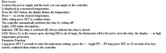
 [b] Der Temperatur-Schalter kommt via eBay innerhalb einiger Wochen direkt aus China. Die Funktionsweise ist simpel: Ein Temperaturfühler misst die Umgebungstemperatur und schaltet bei Über-/Unterschreiten einer zuvor definierten Schwelltemperatur ein Relais ein oder aus. Der Preis ist mit unter vier Euro unschlagbar. Aber es gibt auch eine Downside: Die Anleitung ist, sagen wir mal, ein wenig kryptisch. Hier ist sie, alles klar?!
 [c] Die gängigen PC-Lüfter-Abdeckungen sagen mir nicht zu, also schaue ich mal bei Conrad vorbei. Und siehe da! Im Lautsprecherbereich gibt’s genau das Richtige, und zwar ein recht ansehnliches 105 mm Lautsprecher Schutzgitter. Weiß wäre mir lieber gewesen, aber die Auswahl an weißen Schutzgittern ist überschaubar. Quasi null. Vielleicht sprühe ich das Teil später noch weiß an, aber jetzt geht es erst einmal an den Einbau der Komponenten Ahh und Beh sowie Zeh.
Die mühselig angeschraubte Tür wieder abzumontieren, um dann vernünftig ein Loch für den Lüfter auszusägen, kommt nicht in Frage. Und wo wir gerade beim Thema sind: Ich habe gar keine Stichsäge! Mit dem Fuchsschwanz oder der Zugsäge werde ich hier auch nicht weiterkommen. Aber ich habe einen Dremel Micro 8050 mit allerhand Trennscheiben – das könnte doch klappen, wenn ich statt eines Kreises eine Oktagonform aus der Tür rausfräse. Ich klebe den mit Elektronik gefüllten Innenraum mit Frischhaltefolie ab, um ein Säge-Spän-O-Geddon zu vermeiden und lege los. Allerdings ist nach wenigen Sekunden klar, dass ich mit den mitgelieferten Trennscheiben nicht einmal eine Seite des Oktagons in die 16 mm dicke Tür gefräst bekommen werde. Shoot! Der Payload steigt weiter, denn ich benötige offensichtlich eine Holztrennscheibe. Da gibt es ein passendes Modell  von Dremel mit Karbid-Beschichtung, Modell SC544, ist aber HÖLLE teuer! Geizhals, idealo, günstiger, dann! yeehaa!, für einen akzeptablen Preis bei eBay gefunden. Die Trennscheibe kommt an und ich fräse los. Mein Gott, macht das Handwerken mit vernünftigem Werkzeug SPAß! Geht durch, wie durch Butter. Zumindest die ersten 8-10 mm. Dann wird’s aber doch schwierig, weil der Fräswinkel schräg und damit natürlich nicht optimal ist. Ist quasi unmöglich mit zunehmend spitzer werdendem Winkel komplett durch die 16 mm durchzukommen. Zumal der Dremel Micro zwar ordentlich Gas gibt, aber mangels Drehmoment bei höherem Druck in die Knie geht, um dann letztendlich immer wieder steckenzubleiben. Soviel zu “vernünftigem Werkzeug”. Eine gute Trennscheibe macht aus einem Micro eben keinen Trennjäger. Ok, again what learned. Ich murkse mich von beiden Seiten der Tür in Richtung eines Oktagon-Ausschnitts, was einiges an Geduld erfordert, am Ende aber zum Erfolg führt.
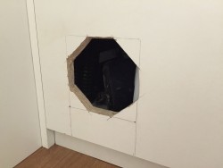
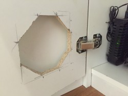
Kanten, Grate und allem, was den Oktagon-Ausschnitt noch hässlicher macht, als es auf den kleinen Bildern zu erahnen ist, rücke ich mit dem Cutter Messer zuleibe. Glücklicherweise wird von den Schnittkanten später (von vorne) nichts zu sehen sein. Der Lüfter wird eingeschraubt, der Temperaturschalter eingeklebt. Anfangs noch mit doppelseitig klebenden PowerStripe-Nachbauten von Aldi (wie im folgenden Bild zu sehen), später dann professionell mit einem dicken Kleks Heißkleber.
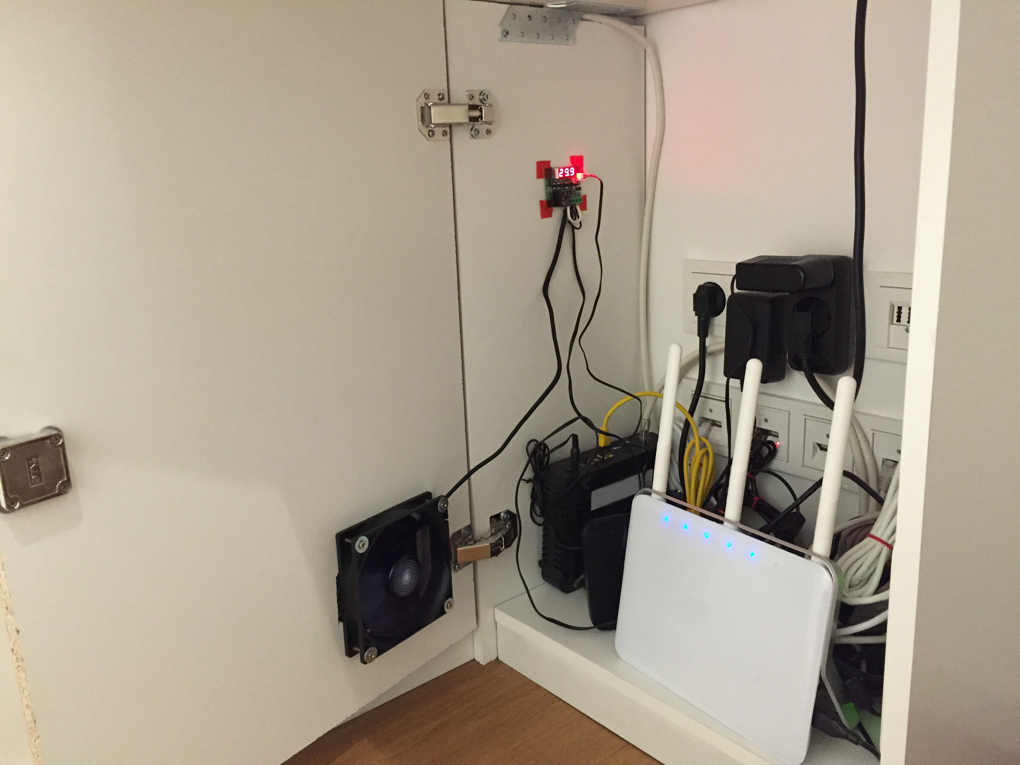
Die Verkabelung des Lüfters mit dem Temperaturschalter sieht wilder aus, als sie ist. Das folgende Schaltbild zeigt, wie die Komponenten miteinander verbunden werden müssen. Der Temperaturschalter ist so konfiguriert, dass er bei 30° Grad Celsius das Relais durchschaltet und damit den Lüfter in Betrieb setzt. Bei Erreichen von 28° Grad wird der Lüfter wieder ausgeschaltet.

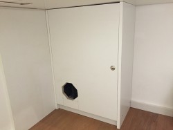
Vorne wird noch das Lautsprecher Schutzgitter aufgeschraubt und das Schränkchen ist fertig.

Ahh, doch noch nicht ganz. Nach einigen Tagen Betrieb zeigt sich, dass der “Silent”-Lüfter nicht Silent genug zu Werke geht. Als hoffentlich finaler Schritt muß jetzt noch die Drehzahl runtergeregelt werden. Jetzt darf ich mein Grundlagenwissen der Physik aus der Klamottenkiste holen, um den benötigten Widerstandsbereich eines Potentiometers und dessen nötige Verlustleistung zu berechnen. Ich wackel zum Conrad, um nach sehr, sehr, sehr vielen Jahren mal wieder an der berühmten Bauteiletheke zu stehen. Das Glück ist mir hold, denn ich erwische einen sehr freundlichen Berater, der mich auf den rechten Widerstandspfad führt und mir anschaulich erklärt, dass ein Poti mit 1 Watt Verlustleistung eine kostspielige Angelegenheit werden würde. Stattdessen lautet seine Empfehlung, einige 1 Watt 10 Ohm-Widerstände zu nehmen und diese so lange in Reihe zu schalten, bis die gewünschte Lüfterdrehzahl erreicht ist. Ein axellenter Tip und das Ergebnis der Lüsterklemmenreihenschaltung ist im linken Bild gefolgt vom Schaltplan zu sehen.


Ich habe fertig.

Möter – halb Mensch, halb Löter und der Lego Todesstern
Die Worte mir fehlten und sprachlos ich war: Den Lego Todesstern sie mir schenkten! Die Macht von Castle Grayskull Star Wars, immer noch stark sie ist. Und jeder Einzelne der auf 50 Tüten verteilten 3803 Steine – eine Freude er war.
| Projektsteckbrief “Todesstern” | |
|---|---|
| Zeitaufwand | ca. 25-30 h |
| Material | Lego Todesstern |
| Skills | Feinmotorik, Klötze stecken |
| Werkzeug | Augen, Hände |
Der Todesstern ist in einer imposanten Big-Badda-Boom-Kartonkiste verpackt. Neben einer großen Menge an Tüten mit den 3803 Lego-Steinen befindet sich auch ein DIN A3 (sic!) Aufbauhandbuch in der Packung. Die Bebilderung ist vorbildlich, wenngleich an manchen Stellen genaues Hinschauen zu empfehlen ist, um die not(false) Steine an die ~1==-2 Stellen zu setzen.
Mit den Lego-Männchen ging es los. Luke Skywalker, R2D2, Darth Vader, Prinzessin Lea, der Imperator etc. pp. – all die guten alten Freunde sind vertreten. Die erste, frühe Erkenntnis: Man verbringt mehr Zeit mit dem Suchen von (Klein-)Teilen, als mit dem eigentlichen Aufbau.

Der Aufbau erfolgt natürlich von unten nach oben. Die Grundplatte steht, die erste Ebene ist noch im Rohbau.

Erste Ebene abgeschlossen, zweite Ebene im Aufbau. Die Schrottpresse vorne links im Bild ist schon gut zu erkennen.

Laserkanone ist auf der zweiten Ebene montiert. Dritte Ebene im Aufbau.

Und nach einer ganzen Menge Baustunden ist das Werk vollbracht. Der Todesstern ist fertig. Und er sieht gut aus!
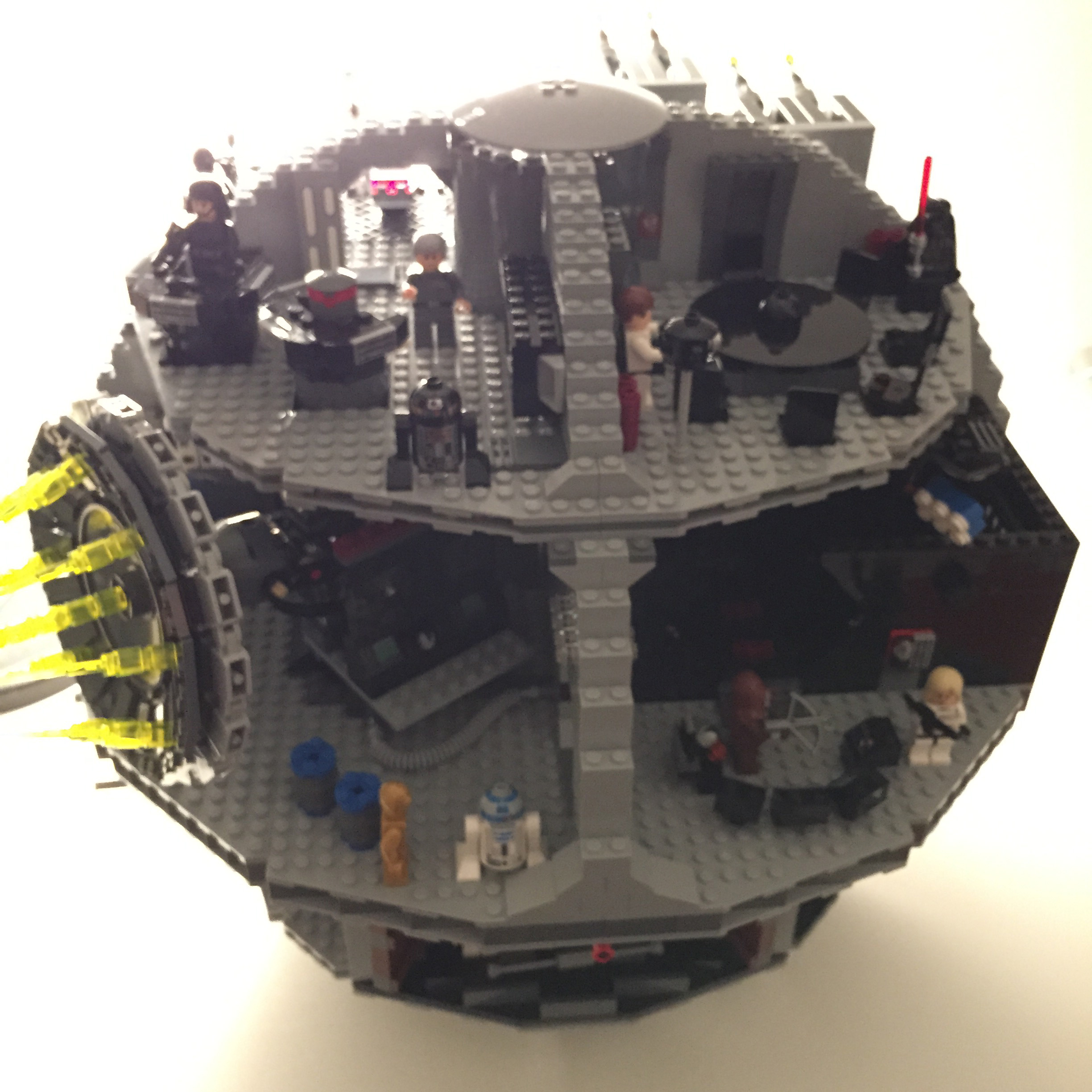
An dieser Stelle noch einmal mein herzlicher Dank allen Schenkenden! Joy and happiness! 🙂 Kommen wir noch zu der Frage, was der Lego Todesstern mit Mötern und Makern zu tun hat? Nichts! Denn das buchstabentreue Zusammenstecken von Lego-Steinchen nach einer bebilderten Anleitung … hat nur bedingt etwas mit DIY und selber bauen zu tun.
Dennoch markiert der Todesstern irgendwie mein Entrée in die glückliche Gemeinschaft Blei- und Flußmitteldämpfe schnüffelnder Löter, Bauer und Programmierer. Auch wenn beim ersten richtigen Make-Projekt gar nicht gelötet wurde: Da ging es um den Bau eines Unterschranks, der die Hauselektronik als da wären Router, Kabelmodem, DECT Basisstation & Co. aus dem sichtbaren Bereich verbannen sollte.