
How to restart iPhone 8 (Plus|X) when you can’t shut down
The process of restarting your iPhone has changed with the advent of the iPhone 8, iPhone 8 Plus or iPhone X.
Such a restart, or hard reset, is necessary if your iPhone is acting weird like you are not able to shut it down by long pressing the side button or you can’t start apps etc.
The force-reboot is no longer achieved by pressing the side and home button simultaneously. Now you have to use the following sequence:
- Press the volume up button once.
- Press the volume down button once.
- Press and hold the side button until the Apple logo appears (approx. ten seconds).
That’s it, your iPhone should reboot. In case you protect your iPhone using a PIN, which is recommended, you will have to enter your PIN after reboot.

Nightlight Late-Night Edition
 This project powers electronic components (5V) with a mains supply circuit (230V > 5V) that is connected to a power plug (230V). If you are going to build this, make sure that you know what you do. In case of doubt, consult a skilled person that is familiar with mains voltage or use a safe power source like a line adapter or batteries.
tl;dr A nightlight based on a reworked Thingiverse design with Arduino-controlled LED light effects, touch sensors, and a piezo buzzer humming the first notes from the Imperial march. Watch the video to see it in action. Detailed instructions start below video.
Bragging rights
 The rocket nightlight was presented in the German MAKE magazine 06/2016 as a community project. Thank you! 🙂
The link or a click on the picture take you to the table of contents of issue 06/2016. If you have questions concerning this project do not hesitate to contact me! <foobar@zeropage.io>
Project Description
You can find a great design for a LED nightlight with various emblems or logos like Stormtrooper, Superman, Punisher, etc. on Thingiverse. This design is based on a 3D printed case with a transparent and extruded inlay of the emblem/logo in the lid. The case has a hole on the backside to have an external power supply feed the internal light source, e.g., an RGB light stripe or similar.
I reworked this design to create a nightlight that
- does not need an external power supply, i.e., has a plug and can be directly plugged into a wall socket
- has touch switches to easily adjust the brightness, light effects (or modes), colors etc.
- uses a piezo buzzer to acknowledge touch switch triggers and to play the first notes from the Imperial March when plugged into a socket (a little annoying, but can be switched off;-)
- utilizes a mounting platform for six RGB LEDs that can be easily inserted into the case
- fixes some minor issues in the original design (displaced inlay and mounting hole)
- comes with a variety of light effects like fixed colors, strobe, or cyclone chase
Payload
1 x Arduino Pro Mini 5V 16MHz // Merchants on eBay offer a plethora of pro minis. Take care when ordering: The pro mini is available as 3,3V and 5V as well as 8MHz and 16MHz versions. Moreover: Many vendors are located in China; shipping may take a long time to your home country.
1 x Piezo buzzer // One of these (eBay) should work.
1 x Power supply // I used this EMSA050120, 5 V-/1,2 A from Pollin to harvest the mains supply circuit and the plug.
4 x 3D printed part // These parts comprise a case, an LED holder, a plate (or lid) and an emblem/logo. You will find the 3D templates as STL files on Thingiverse.
6 x RGB LED // The WS2812b have a nice color range and are usually cheapest when bought as an LED stripe. I had some spare LEDs from another project. You can order them on eBay or here (1m stripe, Roboter Bausatz Shop).
4 x M5, 16mm counter-sunk screw
1 x Software // The software for the Arduino is available in my Nightlight Late-Night Edition repository on GitHub.
Moreover a Dremel or similar to cut open the mains adapter, pliers, rasps, wires, some metal splints for the touch sensors, and, of course, a soldering iron.
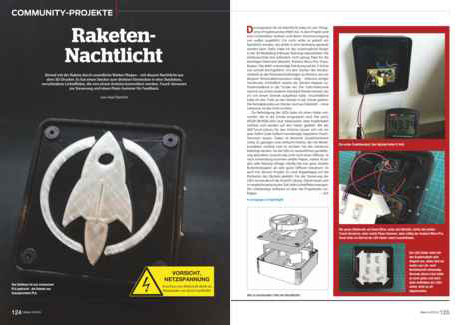
Nightlight 3D Parts
The nightlight consists of four 3D printed parts; cf. the sandwich picture showing the different layers.
From bottom to top: 1) Case to host the mains supply circuit, Arduino pro mini, piezo buzzer, LEDs, touch switches, cables, and the plug. 2) LED holder. 3) The top plate and 4) the extruded emblem inlay.
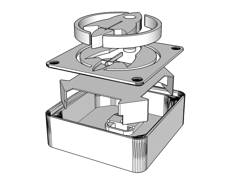
3D Part 1: The Case
The case from the original design was only 13mm high (inner height) and, thus, not tall enough to host the electronic parts. I had to import the STL file into SketchUp and stretch the case on the z-axis to an inner height of 25mm. That gave me just enough space to squeeze the LED holder above the mains supply circuit into the case and still have 2 or 3mm distance from the top plate. The more space you have between the LEDs and the plate, the better the light will be diffused. But I did not want the nightlight to be more bulky than necessary so 25mm inner height had to suffice.
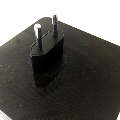
Increasing the height was the easy part. Designing the plug holder on the backside of the case was more difficult. I first measured the dimensions of the plug as precise as possible, then started to design a plug holder with SketchUp.

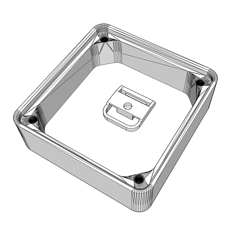
It took a couple of iterations and an according number of test prints until, finally, the plug snapped into the plug holder with a satisfying “click”. The plug fits so tight that I consider it to be unremovable without destroying the case. And I may add that this is by design since we are dealing with 230V AC power and the nightlight must be impenetrable by adventurous kid’s hands.
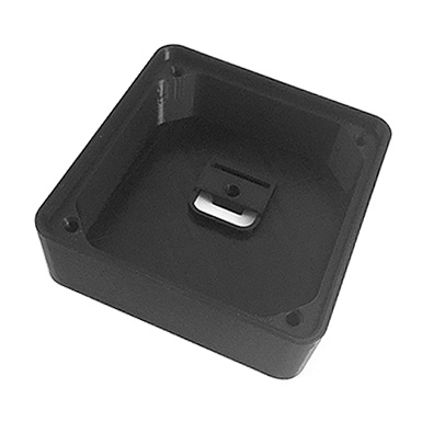
The case was printed with black REC PLA at 210°, bed temperature 60°, no support, 0.16mm height, 1.2mm wall thickness, and 66% infill. It depends on your 3D printer’s bridging abilities if the plug holder will be ok without support. If unsure, print the case with support turned on.
3D Part 2: The LED Holder
I wanted the LEDs in the nightlight to be on a planar surface to get an even illumination. The idea was to construct an LED holder in SketchUp that tightly fits into the case without gluing, is rather stable, and has legs to stand on. The images show what I came up with.
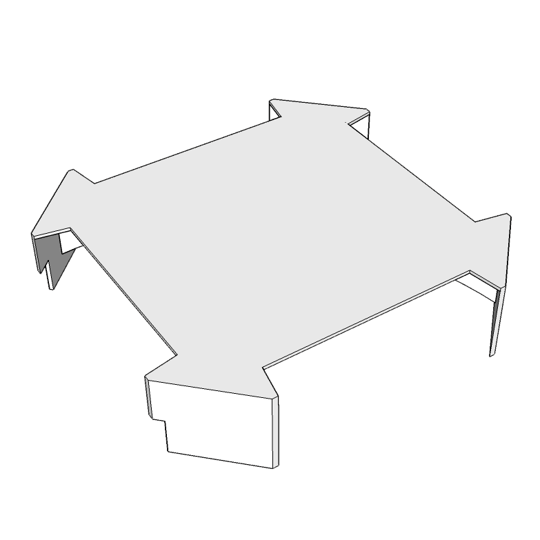


Luckily, the LED holder nearly immediately matched all of the above mentioned criteria. I chose white innofil3D PLA for the print since a white background looked best behind the semi-transparent inlay.
3D Part 3: The top Plate
The plate was printed with black REC PLA and the same print parameters as for the case (210°, bed temperature 60°, no support, 0.16mm height, 1.2mm wall thickness) except that infill was set to 100%. I did not want any light to escape through the plate. With a proper number of top and bottom layers 100% infill with black PLA might be an extreme overkill but I played it safe.


With 100% infill the plate came out rock solid which has another advantage: Some parts might need to be sanded so that the extruded emblem/logo wil fit into the plate. The more solid your parts, the better they can be sanded.
3D Part 4: The Emblem/Logo
The extruded rocket inlay was printed with transparent innofil3D PLA. You will notice that “transparent” is in no way comparable to acrylic glass or alike. Moreover, parts printed with this PLA look yellowed; like they have been exposed for too long in the sun. Nonetheless, this kind of transparency is the best you can get with current fused deposition modelling (FDM) based desktop 3D printers and PLA. Nylon and other filament materials might yield better results but they are more difficult to print and handle.
Infill was set to 22%. You will see the honeycomb pattern, or whatever type of infill you chose in your slicer, with such a low infill value. But more infill also means losing transparency. I was fine with 22%.
Avengers assemble!
Let’s put the hardware together.
Complete the Plate
 The transparent emblem/logo has to be merged with the plate. Depending on the design there might be a couple of “loose” parts from the plate print that need to be inserted into the emblem/logo first. Rasps and sanding paper are your best friend in this step since the parts will most likely not fit straight off the 3D printer. While 3D prints are usually pretty nice, there are limits to the precision you can expect from FDM prints. The rocket has only one loose part which is the round window. That one is pretty easy to insert. If not, rasp and apply mild force. Do not apply too much pressure to the small parts – they might break or damage the plate. If in doubt, sand more and re-try often. It will finally fit. If all loose parts are pushed in the emblem/logo you will want to merge the emblem/logo with the plate. That might need some sanding too. The small and tall middle wing of the rocket will most likely need some sanding. Be very careful since it can break off easily. Carefully push the transparent part into the plate. A vise or a hammer might come in handy, depending on how brave you are. This step requires patience.
Disassemble the Power Supply
As mentioned in the Payload-section I used a very cheap EMSA050120 power supply from Pollin to harvest the mains supply circuit and the plug. The case turned out to be very intractable and successfully resisted my attempts to pry it open it with a screw driver or pliers. I could have tried to pop it open in the vise but did not want to risk damaging the PCB/electronics inside. Well, let’s mill it open – Dremel time!


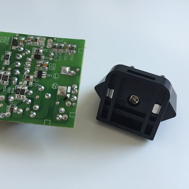
Caveat: Always mill with safety glasses and use protective gloves. The picture is just for demonstration purposes. Milling plastic produces foul-smelling, and most likely toxic, fumes. Do it outdoors. The picture in the middle shows the mains supply circuit along with the plug. In the next picture you can see the backside of the supply circuit with the big L- and N-conductance pads on the right-hand side of the PCB.
Solder Wires on Plug
The plug will be connected with solid copper cables to the L- and N-conductance pads of the mains supply circuit.
Before we can solder the cables two small plastic bars have to be removed from the plug. I use pliers to simply break them off. After that I start to solder the cables on the plug’s connection pads (to the left and right of the middle screw). Or I tried because this turns out to be an epic soldering fail. I try a dozen times but can’t get the, sorry, GODDAMMIT cables to solder-join with the pads. The pads literally refuse to be soldered! But resistance is futile and a couple of search engine queries later I seem to be wiser: The pads are made of stainless steel which is pretty hard to solder with normal tin-solder. If not impossible at all. What I need is soldering fluid, something like this (Conrad).


If you read the soldering fluid’s hazard notes, well, you do not really want to use this stuff: Serious chemical burns of skin and eyes, irritating to the respiratory system, and so on and so forth. Zinc chloride is no fun. Keep away from children! After some more failed attempts even with the soldering fluid I learned that the pads need much more heat to join forces with the cables than I was used from soldering usual electronics stuff. So, finally, I got two nice solder joints. FTW!
Drill Holes for Touch Sensors
 It is always a good idea to think before you act. And I wish I’d done that before printing the case since I forgot to add two 4mm holes for the touch sensors on the right-hand side of the case! Facepalm! Printing the case again just because two holes were missing was not an option. But we are not only apt with additive but also with subtractive manufacturing: I drill the holes with a 3mm wood drill and get a perfect diameter after some minor rasping. PLA is fairly easy to drill, e.g. compared to acrylic glass. But you may have to lift the drill from time to time to remove excess plastic. Wood drills are designed to automatically forward the excess wood to the top of the drill and out of the drill hole. When you drill PLA or other plastic materials it tends to melt and get stuck on the drill. The slower you drill, the better. Applying some drops of water or sewing-machine oil is said to help (not tried so far).
Connect Mains Supply Circuit to Plug
In this step we connect the mains supply circuit to the plug and fix the circuit in the case.
First pop the plug into the case’s plug holder. Since the copper wires are pretty rigid it is a good idea to shorten and bend them properly before soldering the wires to the mains supply circuit.
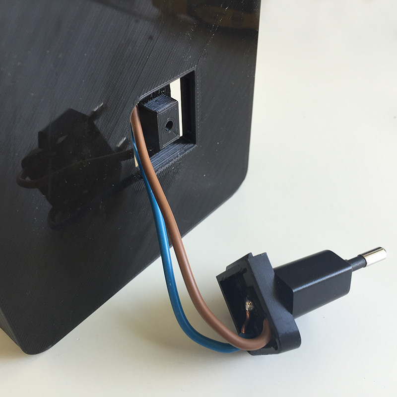


Solder the mains supply circuit’s L-conductance pad to the brown copper wire. Repeat with the N-conductance pad and the blue wire. Finally, attach the mains supply circuit to the bottom of the case. You can see the black and red 5V power supply cables on the left-hand side of the mains supply circuit. We will use these later to power the LEDs and the Arduino microcontroller.
Attach LEDs to LED Holder
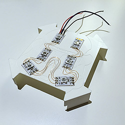 I decided to use six WS2812b LEDs and arranged them on the holder in a pattern that showed the most even illumination level during my tests. In case you’re a Lumen junkie there is enough room to cramp more LEDs on the holder. The LED strips usually come with sticky tape on their backside so gluing them on the holder is easy. After that I used 0.15mm enamelled copper wire to solder the connections between the +5V, GND and D
Prepare the Touch Sensors
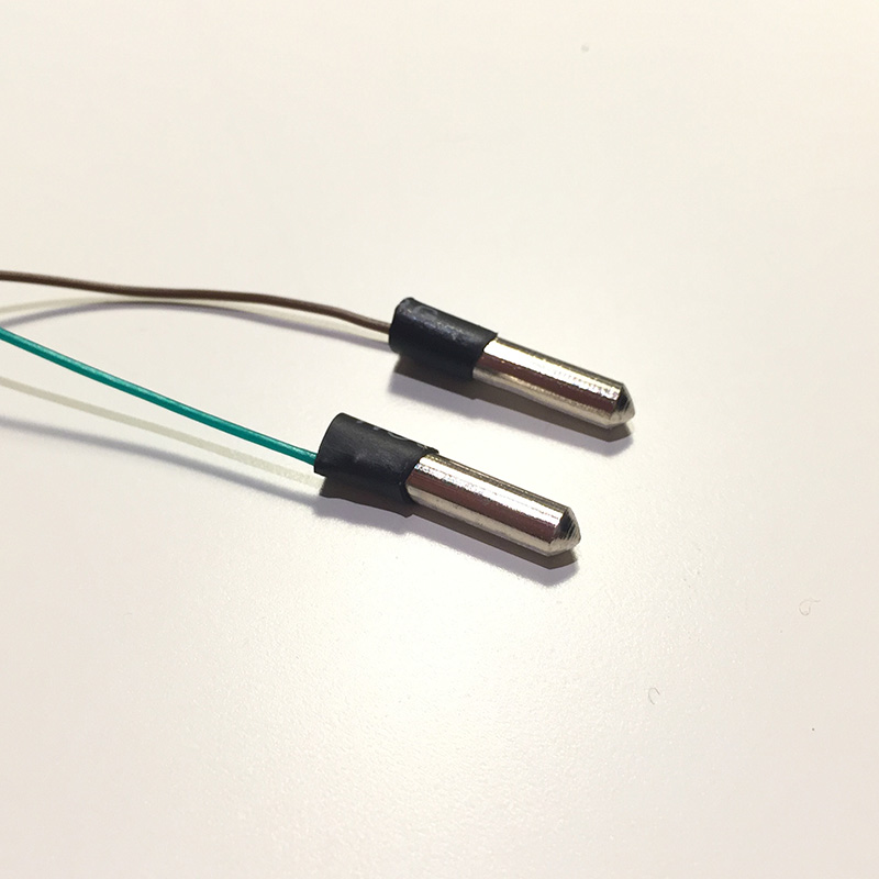 This nightlight requires two touch sensors to control its various functions. The Arduino library ADCTouch makes it very easy to add touch sensors to a project. You can connect nearly everything that changes its capacity when touched to an arbitrary analogue pin of the microcontroller and have that thing act like a touch sensor. In this project I use two small metal splints that will be stuck and glued in the drilled holes on the right-hand side of the case. To connect the splints to the Arduino I have to solder wires to them. Since they are made of stainless steel, I have to use soldering fluid again. One drop on each splint, plenty of heat, a little tin solder, and some heat shrink tubing later the two touch sensors are ready.
Wire it up!
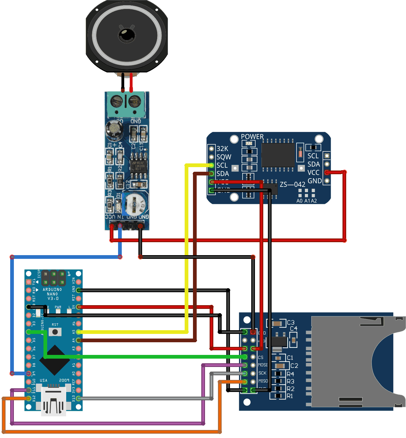
The Fritzing breadboard view shows how the electronic components are wired up to the Arduino pro mini.
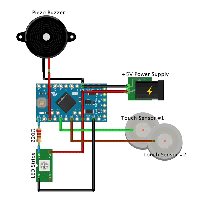
You can choose different pins on the Arduino by adjusting the Arduino Sketch accordingly.
- +5V from the power mains supply circuit goes to the VCC pin while ground is connected to the GND pin on the Arduino.
- The piezo buzzer’s negative pole is connected to the GND pin, the positive pole to pin 12.
- The upper touch sensor goes to pin A0.
- The lower touch sensor goes to pin A2.
- The view shows symbolically only one LED, not the wiring of all six LEDs. The first LED’s Din is connected via a 220 Ohm resistor to pin 10. It is usually advised to use a resistor to cover power spikes that could harm the LEDs. VSS or +5V on the LED is connected to the VCC pin on the Arduino. VDD or ground on the LED is wired to the a GND pin.
That’s how it looks like when all components have been soldered and put into place in the case.


I used hot glue to paste the Arduino and the piezo buzzer on the case. The touch sensors were easier to attach with super glue.
Light and Diffusion
We need to diffuse the light that is emitted by the LEDs so that the transparent rocket is evenly illuminated. I already had some experience with diffusion materials from another project where I tried normal paper with different grammages, frosted acrylic glass, and Ripstop. The results were ok, but not perfect. I followed a hint that white baking paper yields good diffusion results. Unfortunately, I was not able to find white baking paper; only the usual brown one. Next I tried sandwich paper (sic!) and that’s what I found to work best when it comes to LED light diffusion. Of course, it depends on what you are building and especially, how much space there is between the LEDs and the material of the boundary layer. Try different materials and find the one that best suits your needs. However, I like the sandwich paper and, thus, taped a double layer on the backside of the plate. After that, the plate is screwed to the case with four black M5x16mm counter-sunk screws. I wanted screws with no imprint on the screw head but did not pay (enough) attention to the seller’s pictures on eBay. So, always take a very close look at what you intend to buy. 😉 NB: The screws have to cut their way through the holes in the case so it can get tedious to get them in. Use appropriate force. Moreover, the screw heads were bigger than expected so I had to widen the reception holes on the lid’s front side with a hand countersink.
Code is Poetry
All that hardware does not do anything without the proper software. We need a sketch (aka program) for the Arduino pro mini so the nightlight will do the things described in the project description. Two of the used libraries are worth mentioning: The awesome FastLED library to control the RGB LEDs. And the ADCTouch library to easily turn a cable or a splint into a touch sensor. The sketch makes use of the Arduino’s inbuild non-volatile EEPROM to store modes, colors, and other stuff that can be reloaded the next time the nighlight is powered up. The most complicated part of the code is handling the touch sensors. Both sensors react to short (1st function), middle-long (2nd function) and long touches (3rd function) and trigger different functions depending on the touch durations. Sounds complicated, but is not. Or is it?
Upper sensor
- Short touch. Increase brightness of LEDs until maximum is reached (17 steps). Then turn LEDs off.
- Middle-long touch. Immediately return brightness to lowest setting, i.e., one step above zero.
- Long touch. Toggle playing Imperial March on power-up on/off.
Lower sensor
- Short touch. Change color, speed, or whatever of current lighting mode.
- Middle-long touch. Switch to next light mode.
- Long touch. Immediately switch to first light mode, i.e., fixed color.
You can find the code in my Nightlight Late-Night Edition repository on GitHub.
Ready Player One
That was a real fun project and the roket nightlight turned out to be a full success!
Sep 2016, i.f.
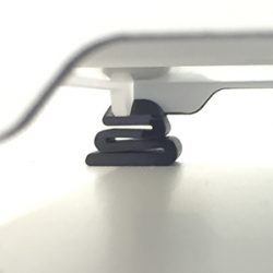
Noise dampening feet for Ultimaker2
3D printers can be quite noisy. Besides a full encapsulation that might also proof valuable if printing ABS there are other ways to lower the volume. One is to reduce the vibration that is transferred from the moving parts of the printer to its case and from there to the table which resonates and, depending on size and material, is likely to subsequently work like a noise amplifier.
This effect can be reduced with noise dampening feet. There are a already lot of dampening feet designs available on Thingiverse or YouMagine so there is no need to design a new one. The Damping foot UM original by Kees de Ligt looks promising.
 The first foot printed well with black REC filament using 0.15mm layer height, 0.8mm shell thickness, 35% infill, support, and with the square side facing the print bed. I use “hotter than normal” settings for the REC PLA: 215° noozle and 70° bed temperature. These temperatures provide nice prints and good platform adhesion with the REC filament. After that I got lightheaded and tried to print the remaining three feet all at the same time. While this is usually not a big deal, the REC PLA filament consistently turns out to be somewhat picky. Too much cooling time between the layers and the prints tend to fail.
This is how the three-at-the-same-time fail looks like.
 Heavily warped edges on the bottom-most print. The first layers of the dampening foot in the middle look ok. But the top-most foot has been utterly destroyed. You’re on the lucky side if you notice such failures early enough to abort the print and, thus, avoid wasting material.
As I took a closer look at the dampening foot that was printed first, I realized that I would need two of the feet “as is” and another two feet mirrored at the y-axis. Only this way all four feet would face the same direction when attached to the printer. So, I should be thankful that the simultaneous print of three feet failed since that would have produced two unmirrored feet. You can easily mirror objects at all axes in Cura: Click the object then hit the mirror button on the bottom left and click on of the Mirror X/Y/Z buttons.
The remaining one foot as well as the y-mirrored two feet print like a charm. Attaching the feet is easy: Lift one corner of the printer and push the corresponding foot underneath this corner. Repeat with all other corners. Done.
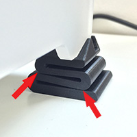 [Update] There is definitely a damping effect resulting in a less noisy soundscape. Good! But after a couple of prints the two rear feet have been tightly compressed so the curvatures of the snake-like construct touch each other. Hence, the damping characteristics of the rear feet are lost. Reason: The 35% infill and 0.8mm outer shell thickness are to weak to support the heavy rear part of the Ultimaker. Solution: Using 1.2mm outer shell thickness and 90% infill yields a new “as is” rear-left foot, and a new y-mirrored rear-right foot that are of heavy duty quality and now easily support the Ultimaker’s rear side.

How to easily use gmail for throwaway mail addresses
Spam, phishing, viruses, bots, ransomware… If you use e-mails as a communication method you are inevitably facing countless annoyances and threats. And the volume as well as quality of these threats is increasing. There is no way to use e-mail and completely and utterly avoid any contact with mail junk. Besides being heedful concerning sender, content, links, and, especially, attachments, there is one thing you can do that may help to decrease the amount of spam and other junk you receive via e-mail: Use throwaway e-mail addresses.
Throwaway e-mail addresses
A throwaway e-mail address is a mail address that is generated for a special purpose and discarded when it has done its duty. There are a couple of options to generate throwaway addresses:
- If you are running your own server or hosting your own domain at an ISP create disposable e-mail addresses by using your mail servers catchall functionality.
- Use an online service that is specialised on disposable mail addresses like throwawaymail.com, guerrillamail.com, or temp-mail.org.
- Use gmail to generate throwaway addresses.
Let’s look at how to use gmail to generate disposable mail addresses.
Gmail: Generate arbitrary e-mail recipients with a “+”
A typical gmail address looks like this
abc@gmail.com
Now, to generate a new e-mail recipient you can add an arbitrary string of characters behind abc preceded by a plus “+” sign, e.g.,
abc+xyz@gmail.com
An e-mail sent to abc+xyz@gmail.com is just as well delivered to abc‘s inbox. And that is all there is to generate arbitrary e-mail recipients with gmail!
Fight e-mail abuse
How do you use a throwaway e-mail address to fight spam? If you register to an online store, say cheapcheapercheapest.com, you would no longer use your regular e-mail address abc@gmail.com but instead something like, e.g.,
abc+cheapcheapercheapest@gmail.com
Now, if cheapcheapercheapest.com got hacked or if they sold your e-mail address to spam-lists etc. potential mail abusers might get hold of this e-mail address which they will use to send their crap to. As soon as spam and other annoying stuff has been sent to abc+cheapcheapercheapest@gmail.com there is just one thing you have to do: Lock e-mails out that are sent to this address keeping your abc@gmail.com inbox clean. Let’s see how to do that with gmail.
Lock them out
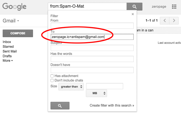
Gmail is able to apply filter rules to incoming messages. These rules use one or more criteria like sender’s e-mail address, addressee, or specific words in the subject to identify an e-mail and apply one or more actions on it like marking as read, forwarding, moving to a folder, or deleting. Let’s define a deletion rule for an imaginary spam e-mail by the sender Spam-O-Mat that has been sent to foobar.io+antispam@gmail.com. This is the e-mail in foobar’s inbox.
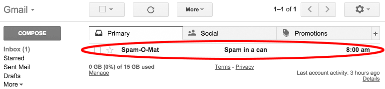
This e-mail is, obviously, very suspicious. We want to see where it has been sent to, i.e., who the exact recipient is. Show the e-mails content by clicking on it. You would see something like this.
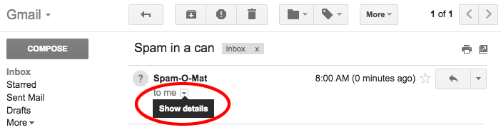
We do need the details so click the corresponding “show details”-button just below the sender’s name.
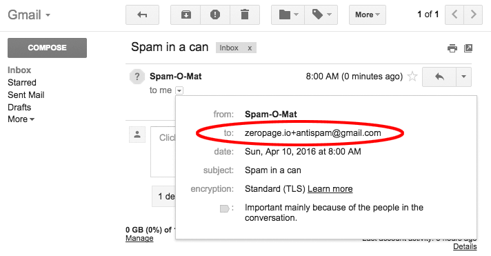
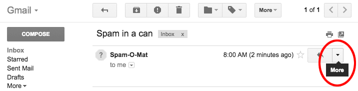
We get a popup window revealing more information about from, to, date, etc. The “to”-field shows who the exact recipient’s address. Here we see that this spam e-mail has been sent to foobar.io+antispam@gmail.com. Apparently, it was a good idea to use a throwaway e-mail address! We will define a filter rule to immediately delete all e-mails sent to foobar.io+antispam@gmail.com. Click the “more” button on the right-hand side of the e-mail header bar.
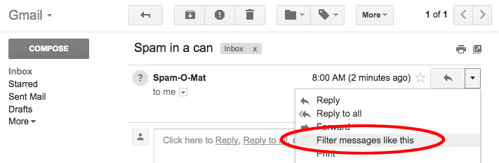
You will see a popup window with a couple of options. Choose “Filter messages like this”.
You will see another popup with the filter criteria. The To-field has already been filled with foobar.io+antispam@gmail.com. Nothing else to do here, just click on “Create filter with this search »”.
The final step where you choose what to do with the e-mail. Activate the option to “Delete it”. I suggest to activate “Also apply filter to 1 matching conversation” too so this new rule is also applied to the e-mail we started from as soon as the filter rule has been created.
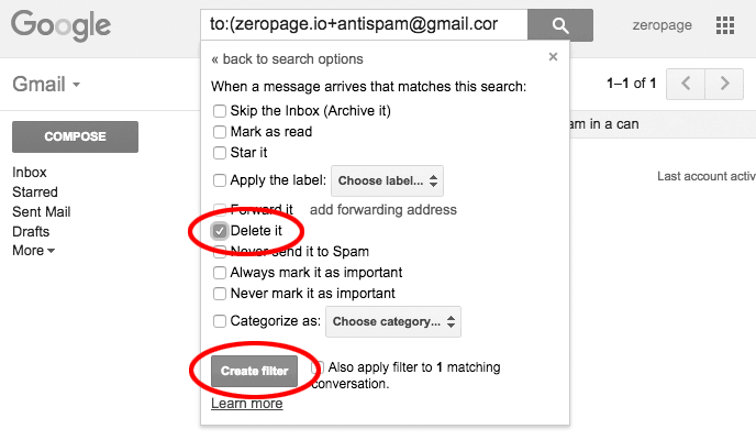
Click “Create filter” when you are done. And you are done.
This looks and reads more complicated than it is. Once you know what to do it’s just a matter of seconds to have a filter rule in place. Keep your inbox clean!

How to add images to your WordPress RSS Feed
I accidentically stumbled upon this unexpected WordPress behaviour. Looking for a solution I came across this post Beitragsbilder im WordPress RSS-Feed einbinden by Tobias Rieder. He explained how to add a few lines of code to the functions.php file to add a post’s featured image to the RSS feed.
Of course, you could install a plugin like “Featured Images in RSS w/ Size and Position” to have the same result. But that would be yet another plugin. And every plugin uses some processing time on your server. Moreover, tinkering the functions.php is how real men do stuff like that. 😉 Add the following lines to your theme’s functions.php. It is advised to use a child theme for modifications like this.
function post_thumbnail_in_rss( $content ) {
  global $post;
  if ( has_post_thumbnail( $post->ID ) )
    $content = get_the_post_thumbnail( $post->ID, 'medium', array( 'style' => '' ) ) . $content;
  return $content;
}
add_filter( 'the_excerpt_rss',  'post_thumbnail_in_rss', 1000, 1 );
add_filter( 'the_content_feed', 'post_thumbnail_in_rss', 1000, 1 );
You can choose the picture’s size to be either full, medium, or thumbnail. Using style in the array you can inject CSS styles, e.g. add a margin or a border to your picture.
Have at it!

RIBB@TACKING Bruce Lee – a C64 game tribute and homage
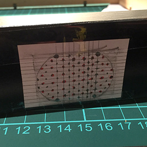
One day end of 2015 I stumbled upon some pretty kewl voxel art by Metin Sevin. Amongst many others like Mario Bros, Pacman, or Donkey Kong, I was immediately fascinated by the 3D rendered Bruce Lee Commodore 64 game tribute picture. I contacted Metin and asked him if his work is for sale and he kindly pointed me to society6 where a lot of his art is available in various formats. If you are interested in Metin and his work you can find out more in this interview at the end of this blog post. Due to some other planned projects based on Ikea Ribba frames I had one 23x23cm frame on stock so the 8″x8″ Bruce Lee art print would fit just fine. Shipment from Illinois/USA took about two weeks and I was ready to go for my art project!
tl;dr Watch the video to see what this project is about. Making of with gory details below video.
Project Description
Take the 8″x8″ Bruce Lee art print and put it in a 23x23cm Ikea Ribba frame. Use an Arduino to play the C64 Bruce Lee game title music at 12am and 7pm. Announce every hour starting with the first 3secs of Carl Douglas’ Kung Fu Fighting song and indicate the current hour by an according number of Yamo’s calls (the green Sumo in the game). Announce a quarter past, half past, and a quarter to with the Ninja’s stick strike sound ringing out once, twice, or thrice, respectively. Finally, add a capacative touch sensor to cycle through all Bruce Lee game sounds by touching one corner of the Ribba frame.
Payload
1 x 8″x8″ Bruce Lee art print from society6.
1 x RIBBA frame from Ikea seems no longer to be available. You could use a 25×25 cm Sannahed frame as a replacement.
1 x Visaton K28.40 8Ω, Price comparison idealo
1 x Arduino Nano e.g. from eBay
1 x LM386 Audio Amplifier Module e.g. from eBay
1 x DS3231 Real Time Clock (RTC) e.g. from eBay
1 x CR2032 battery for DS3231 RTC
1 x SD Card Module e.g. from eBay
1 x SD Card 1GB is sufficient
1 x 5V 1A power supply
Cables, solder and iron, hot-melt gun, screws, (cordless) screwdriver, drill, side cutter, etc.
A 1GB SD would have been sufficient since the WAVE files are very small. Unfortunately, I threw away old small capacity SD cards years ago “…when should I ever need a one or two GB SD card again?” Well, now I know the answer. Thus, I had to use an 8 GB SD card.
Audacity will be helpful to recode the Bruce Lee tunes to the required format.
Howto
Order the Bruce Lee voxel from society6. Wait approximately two weeks until it arrives; might heavily depend on where the item is shipped to. 😉 While waiting: a] Buy a 23x23cm RIBBA frame at your local Ikea. b] Prepare the necessary electronics and code to get the thing up and running.
Hardware
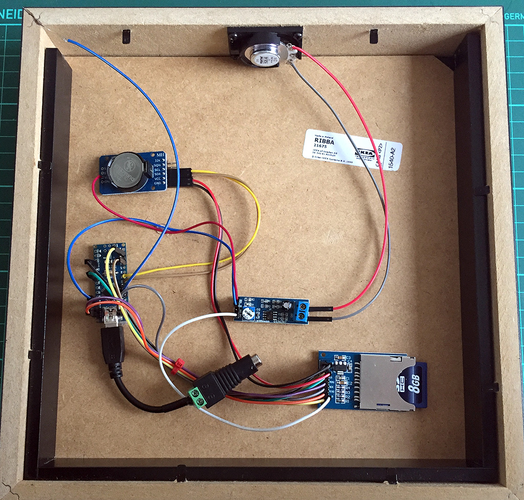
For the hardware part: Glue the required components, i.e. Arduino Nano, amplifier, SD card module, DS3231 RTC w/ CR2032 battery to the back of the RIBBA frame. It might look like this.
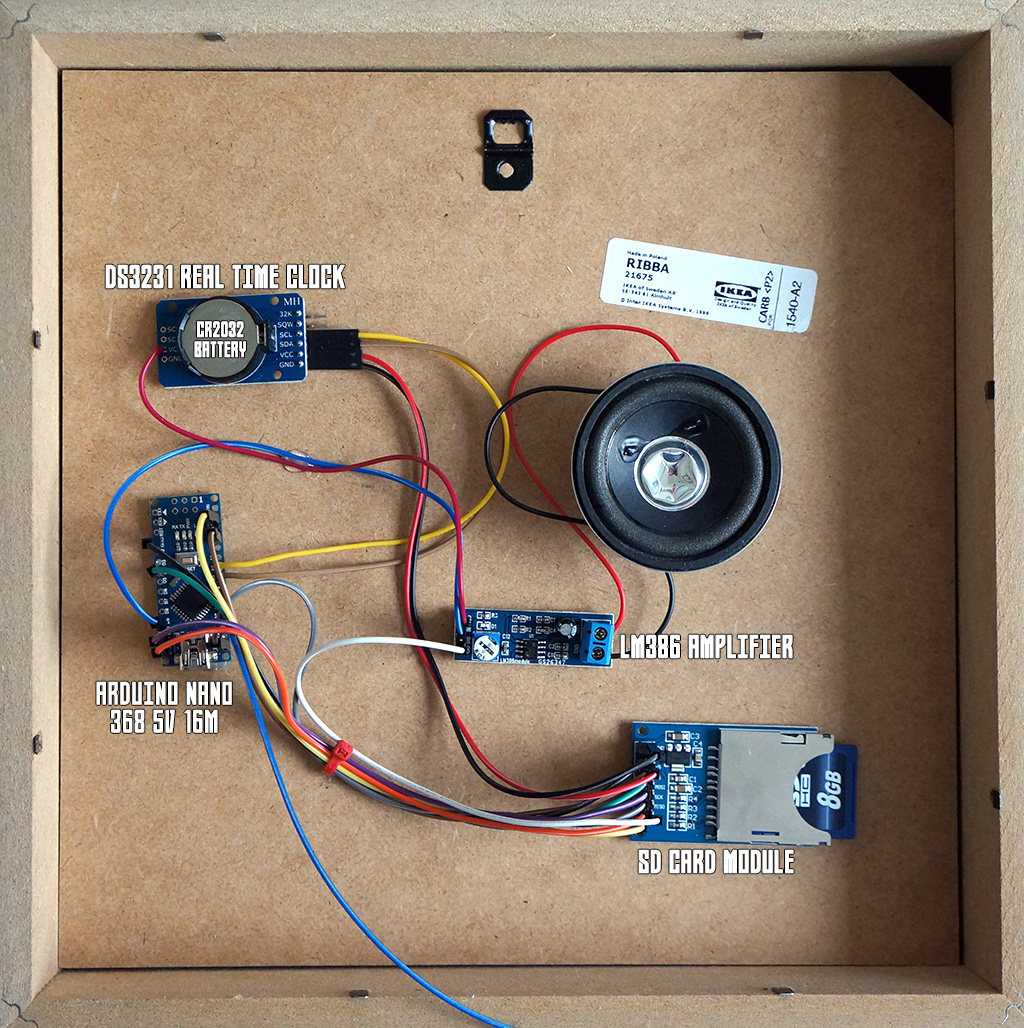
NB: This was my first shot with the loudspeaker directly glued to the backside as can be seen in the photo. My assumption that the – sort of abyssal – RIBBA frame will act as a good resonator
WAS WRONG. When I hung up the picture on the wall for the first time you could barely hear anything. The loudspeaker radiating directly to the wall was nearly completely muted since the sound waves cannot escape the frame.
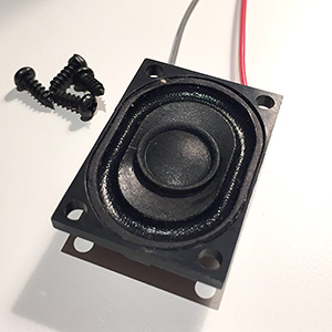 New solution: Drill a plethora of holes into the bottom part of the frame and attach a (smaller) loudspeaker so that its sound waves can go through the holes. There are roughly 3 cm space between the backside (with the components) and the wall-facing side of the frame. Thus, I needed a speaker with a radius of max(3cm). I found an fairly good sounding 2,8x4cm rectangular-shaped speaker from Visaton that would fit snuggly into the available space (cf. picture).
 I created a drill template with the speaker’s exact dimensions by laying a piece of paper on top of it and tracing its contours with a pencil. Old school but works! After that I drew a mesh pattern with a lot of drill holes. That could have been the maiden trip for my drill press…but I went with the cordless screwdriver that did a nice job on drilling the 90+ holes. The template was fixed with sticky tape to the frame before drilling. I covered the whole template with tape to avoid frayed drill holes. This worked pretty good on the template
 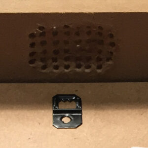 side but not on the inside of the frame. The RIBBA frame is made of chipboard so I lost quiet some material while drilling. You can see in the picture that the inside is not flat anymore but sort of curved due to the lost material. Next time I would apply sticky tape to the inside too.
 The holes needed some afterwork, i.e., burring and removing frayed pieces. The pictures do not show the final stage of afterwork so you will have to trust me that the result was ok. Especially, since the holes are on the bottom side that will, most likely, hardly been seen or looked at when the frame is hanging on the wall. I was happy with the result and moved on to screw the Visaton speaker into the frame with four black and tiny flat-head screws that were giving me a hard screwing time.
This is how the final setup looks like.
Note the blue cable going to the upper left corner?
This is the capacitive touch sensor wire. 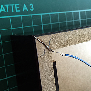 It is basically a piece of zinc coated copper wire bent to a 90° angle and sticked exactly to the corner of the frame using super glue. It was then painted black and soldered to the blue cable to have it connected to the Arduino. With this switch I would later be able to play all Bruce Lee game tunes one after another by repeatedly touching the bottom left corner of the frame. Actually, the ADCTouch-Library used is doing such a great job that the Arduino can react to a finger (or a hand, or some other body part) just coming near to the wire. You can measure changes in the wire’s capacity without even touching it. Awesome!
What’s missing? Yes, details on the wiring. The correct wiring might be hard to find out by just looking at the pictures, not least since my wire color scheme is a bit, eh, inconsistent. So here’s a Fritzing breadboard view of the wiring.
That should cover the most important aspects of the hardware. But all this hardware is nothing without software. Let’s move into the matrix.
Software
Code is poetry
There are more lines of code in the Arduino sketch (GitHub) than needed to implement the behaviour as described in the Project Description. Nonetheless, some of the code is helpful for debugging purposes and some other for fiddling with the TMRpcm Library.
This library is used “for asynchronous playback of PCM/WAV files direct (sic!) from SD card”. The WAVE files must be in a specific format, i.e., 8-bit, 8-32khz Sample Rate, mono. Thus, do not expect Hifi quality! I wrote a separate article WAV-Dateien von SD-Karte mit Arduino abspiele where you will find the gory details about the required file format, how to convert, e.g., an mp3-file using Audacity into this specific WAV-format, how to format the SD card – if required, how the WAV-files have to be named on the SD card (8.3. SFN – short file name from the good ol’ MS-DOS times), and a short Arduino sketch to test the TMRpcm lib.
The ADCTouch library is required for utilizing capacitive touch sensors without any additional hardware.
Debugging with “Serial.print()” is not that funny so we’re using the Streaming library to provide a C++ like << operator that allows constructs like Serial << F( "Current volume is " ) << gVolume << "." << endl; which is very convenient. NB: With the macro F() you put strings in an Arduino's flash memory instead of the sparse static RAM (SRAM) leaving more space for variables and such. The ATmega328 chip found on the Uno has the following memory:
Flash  32k bytes (of which .5k is used for the bootloader)
SRAM   2k bytes
EEPROM 1k byte
Flash is plenty but SRAM isn't - so there is reason to always save SRAM!
Finally, we need the DS3232RTC and Time library to handle the real time clock. Europe will not let go of the daylight saving time (DST) idiocy. Summer time is switched on at the last Sunday in March where 2 o'clock becomes 3 o'clock. Vice versae at the last Sunday in October where 3 o'clock becomes 2 o'clock. We have to recognize the DST so the Bruce Lee cookoo works both in summer and winter. 😉 Thanks to user "jurs" from the German Arduino Forum we have a great European daylight savings time calculation function fIsSummertime() that returns "true" when we're in summer time and false if not.
The Arduino sketch
Sketch also available on GitHub in the RIBBAttacking-Bruce-Lee repository.
Interview with the artist
Metin and I had a nice e-mail-chat while the project was ongoing. There are quiet some analogies in our CVs like being born in the 1970s, growing up with 8-bit computers, adjusting the datassette's azimuth with a screwdriver, hanging out at arcade halls, and - of course - liking minimalistic pixel graphics. Here is short interview with Metin to get you in touch with him as a digital artist and his voxel creations.
Metin, who are you?
My name is Metin Seven, I was born in the 1970s, and grew up in the 1980s with the first 8-bit and 16-bit generations of game consoles and 'home computers', particularly the Atari 2600, CBS ColecoVision, Commodore 64 and Commodore Amiga.
What is your artistic spectrum, i.e., what kind of art do you make/prefer?
I'm a die-hard digital artist. I used to draw on paper as well, but I prefer the flexibility of the digital screen. I started creating pixel art for Amiga demos in the late 1980s. That soon evolved into creating pixel graphics for commercial games, television commercials and children's animation series in the 1990s, all done using software like Deluxe Paint and Personal Paint on an Amiga. Since the late 1990s I've shifted towards 3D graphics creation, but pixel art will always keep a special place in my heart.
Why retro games and what is your reference to this genre?
Ever since I was a little kid I was enchanted by the magic glow of the digital screen. I used to hang out at arcade halls, playing the first 8-bit games, such as Donkey Kong, Lady Bug, Pac-Man and Pengo. When I was not playing them myself, I could stare at people playing the games for hours. The first pixel graphics had this pure, iconic quality because of the low resolution restrictions for sprites and such. It's great to see that atmosphere return in the current wave of minimalistic pixel art games for mobile devices.
Did you have decent experiences with the C64?
Definitely. During my school days I spent just about every afternoon and evening playing Commodore 64 games, first loading them using the Datassette tape recorder, adjusting the azimuth when necessary. After a while I bought a floppy disk drive. LOAD "*",8,1 😀
How did you come to create voxel pictures? Where does the idea come from?
During the 2000s I created a lot of stylized 3D illustrations for printed magazines and newspapers. My use of shapes and colors reflected my game pixel art background, and gradually my illustration style became more elementary, until I arrived at a point that fully made sense — a blend between pixel art and 3D artwork: voxels. It was then that I decided to start paying tributes to my childhood love: 8-bit and 16-bit games.
Can you tell us something about the voxel creation process?
My first voxel images were created in 3ds Max in the mid-2000s, extruding blocks of quadrangular polygons. That was quite a hassle, and I was eager to find a dedicated voxel editor. I found that in the shape of Paint3D for Windows. I got in touch with the coder and suggested a number of features, which he kindly implemented.
When I switched to Mac OS X in 2014, I started using Qubicle, also a versatile voxel editor. I guess MagicaVoxel would be the tool of my choice today, but to be honest I've become a bit saturated when it comes to voxel creation, although there’s a good chance I'll return to it some day.
Where should we go if we'd be interested in more from you?
The best starting place is my portfolio site metinseven.com, there you will find links to my online shops, offering 3D prints, 2D art prints, stock 3D models and stock illustrations.
Many thanks for this interview, and my sincere compliments to you regarding your clock creation based on my voxel tribute to the classic 8-bit Bruce Lee game.
The pleasure was all mine! Keep on the good work!

i.f.
WAV-Dateien von SD-Karte mit Arduino abspielen
 Eins gleich vorweg: Hifi-Qualität darf man von der hier beschriebenen Lösung nicht erwarten. Aber als Low-Budget-Player für einfache Zwecke reicht es auf jeden Fall. Habe ich beispielsweise hier im Kunstprojekt RIBB@TACKING Bruce Lee – a C64 game tribute and homage verwendet.
Was man braucht
Natürlich einen Arduino; der hier beschriebene Aufbau wurde mit einem Uno getestet. Alle 328er basierten, also auch Nano, LilyPad, Pro etc. sollten gleichermaßen funktionieren.
Da die WAVE-Dateien irgendwo abgespeichert sein müssen, bietet sich ein SD Kartenleser an. Es gibt Breakout Boards mit Micro-SD-Karten Slot oder andere Shields, auf denen solch ein Slot bereits integriert ist, bspw. das Ethernet-Shield. Hier kommt ein sehr einfacher 1 EUR SD-Kartenleser von eBay zum Einsatz. Dazu eine (alte) SD Karte.
Damit man etwas hört, braucht es einen Verstärker. Bryan beschreibt in diesem Blog-Artikel, wie man mit einem einzigen Transistor nebst Widerstand (4,7 kOhm) einen simplen Verstärker zusammenschustert. Der BC548B hat nicht ausreichend verstärkt. Mit dem 2N3904 (eBay) macht es mehr Spaß.
Dazu natürlich ein Lautsprecher, da hatte ich noch einen mit 0,25 Watt 4 Ohm auf Halde liegen.
Verkabelung / Aufbau
Die Anbindung des SD-Kartenlesers erfolgt über die Hardware SPI Pins des Arduino. Welche Pins das genau sind, hängt vom Arduino-Typ ab. Die hier gezeigte Verkabelung sollte für alle 328er Typen (Nano, Uno, etc.) funktionieren. Chip Select ist frei wählbar; vgl. auch der weiter unten stehende Arduino Sketch. Die Schaltung auf dem Breadboard ist der erwähnte Ein-Transistor-Verstärker. Wenn man hier den Widerstand zwischen Arduino-Ausgang (Pin 9) und der Transistorbasis zu klein wählt, kann man nach kurzer Zeit auf dem Transistor Eier braten, da zu viel Strom durch die Collector-Emitter-Strecke fliesst.

Wagemutige können den Widerstand einfach mal ganz weglassen und sich an einer, dann, recht ordentlichen Beschallung nebst Transistorheizung erfreuen. Das sei hiermit also ausdrücklich nicht empfohlen.
| Kartenleser PIN | Arduino PIN | Was ist das? |
|---|---|---|
| GND | GND | Ground |
| +5V | 5V | Volle Power! 🙂 |
| MOSI | 11 | DATA, MOSI DATA, SDA, Hardware MOSI |
| MISO | 12 | MISO, Hardware MISO |
| CLK | 13 | CLK, SCL, Hardware SCK |
| CS | 4 | CS, Chip Select |
| GND | GND | Ground |
In der Tabelle ist die PIN-Verkabelung noch einmal aufgeführt. Der verwendete SD-Kartenleser hat zwei GND-Anschlüsse und funktioniert auch nur zuverlässig, wenn tatsächlich beide mit Masse verbunden werden. Der Lautsprecherausgang ist, ebenso wie Chip Select, über den Arduino Sketch frei wählbar (hier PIN 9).
Zwei Blog Posts haben bei Verkabelung und Inbetriebnahme gut geholfen. Zum einen dieser Beitrag bei maxoffsky.com sowie insbesondere diese Anleitung auf instructables.com.
Format der SD Karte
Die verwendete SD-Library unterstützt prinzipiell die Dateisysteme FAT16 und FAT32. Es wird jedoch empfohlen, wenn möglich, FAT16 einzusetzen. Bei mir hat’s mit einer FAT32-formatierten SD-Karte nicht funktioniert, daher wollte ich sie “mal eben” auf FAT16 formatieren. Das geht auch mit MacOS Bordmitteln, ist aber etwas komplizierter, als erwartet. Dieser Post im Adafruit-Forum beschreibt den Weg in Englisch; hier in knappem Deutsch:
- SD-Karte in den Mac stecken.
- Terminal-Fenster öffnen. Bspw. mit CMD+Space, dort “terminal” tippen und Return.
- Geräte-ID finden. Dazu im Terminal
dfgefolgt von Return eingeben. Es erscheint eine Filesystem-Übersicht, die unter anderem die folgenden Informationen enthält. Ganz unten ist die SD-Karte “NO NAME” zu sehen. Wer auf Nummer sicher gehen will, gibt seiner Karte einen eindeutigen Namen. Dann kann man sie in dieser Übersicht schneller finden. Die in den folgenden Schritten benötigte Geräte-ID lautet/dev/disk3s1.Filesystem Used Available Capacity iused ifree %iused Mounted on /dev/disk1 909007896 65197032 94% 113689985 8149629 93% / devfs 371 0 100% 642 0 100% /dev map -hosts 0 0 100% 0 0 100% /net map auto_home 0 0 100% 0 0 100% /home /dev/disk3s1 20928 4172608 1% 512 0 100% /Volumes/NO NAME
- SD-Karte unmounten (nicht auswerfen!). Im Terminal
diskutil unmount /dev/disk3s1gefolgt von Return eingeben. Dabei disk3s1 natürlich durch die eigene Geräte-ID ersetzen. Erfolgreiches unmounten wird bspw. mitVolume NO NAME on disk3s1 unmountedquittiert. - FAT16 Filesystem auf SD-Karte schreiben. ACHTUNG! Der folgende Befehl löscht alle Daten auf dem Gerät. Wenn die Geräte-ID nicht die von der eingesteckten SD-Karte ist, sondern bspw. aus Versehen die der eingebauten Festplatte, dann wird diese gelöscht. U have been warned.
Folgendes Kommando im Terminal eingeben und nicht vergessen die Geräte-ID anzupassen.newfs_msdos -F 16 /dev/disk3s1
Ich habe alle Warnmeldungen, die der Befehl produziert hat, konsequent ignoriert und als Lohn der Mühe im Anschluß eine lauffähige FAT16-formatierte SD-Karte gehabt.
Format der WAVE Dateien
Die Library TMRpcm benötigt zum Abspielen die WAVE-Dateien im Format acht Bit, acht bis 32 kHz Sample Rate, mono. Im WIKI zur Library werden zwei Wege beschrieben, wie man iTunes oder Audacity verwenden kann, um aus dem musikalischen Quellmaterial das Zielformat zu generieren. Audacity ist prima, und so geht’s damit:
- Hauptmenü “Tracks”, dort “Stereo Track to Mono” wählen.
- Unten links die “Project Rate (Hz)” mit dem Popup auf 8000, 11025, 16000, 22050 oder 32000 setzen. Je niedriger die Sampling Rate, desto schlechter die Qualität.
- Hauptmenü “File”, dort “Export Audio…” und im File Selection Dialog unten als Format “Other uncompressed files” wählen. Dann “Options…” klicken und als Header “WAV (Microsoft)” sowie bei Encoding “Unsigned 8-bit PCM” wählen. OK.
- Datei mit “Save” speichern.
Dateinamen
Dateinamen müssen zwingend dem – aus alten MS-DOS Zeiten bekannten – 8.3-Format folgen, also maximal acht Zeichen für den Dateinamen gefolgt von Punkt und einer Endung mit drei Zeichen beispielsweise “NAME0001.EXT”. Der Dateiname kann kürzer als acht Zeichen sein, in keinem Fall aber länger. Die Wikipedia widmet dem 8.3 short filename (SFN) tatsächlich einen eigenen Artikel.
Arduino Sketch
Der folgende Sketch bindet zunächst die benötigten Libraries ein, definiert Chip Select- und Lautsprecherausgangs-PIN, initialisiert die SD-Karte mit SD.begin() und spielt im Erfolgsfall die Wave-Datei snakec16.wav direkt von der SD-Karte ab. Im Fehlerfall wird eine kurze Meldung über den seriellen Monitor ausgegeben.
#include
#include
#include
#define CHIP_SELECT_PIN  4
#define SPEAKER_PIN      9
TMRpcm tmrpcm;

void setup( ) {
  tmrpcm.speakerPin = SPEAKER_PIN;
  Serial.begin( 9600 );
  while ( !Serial ) /*mt*/ ;
  if ( !SD.begin( CHIP_SELECT_PIN ) )
    Serial.println( "SD fail" );
  else {
    tmrpcm.play( "snakec16.wav" );
    delay( 5 );
  }
}

void loop( ) {
}
Wenn alles läuft…
…dann sollte das in etwa so aussehen, wie in dem Video.
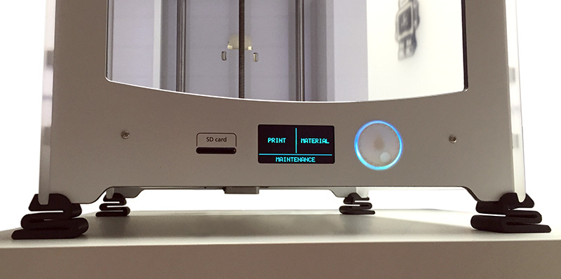
OLED 0,96″ Zoll Display an den Arduino anschließen
Bei eBay, Aliexpress & Co. gibt es zahnlose Mini-OLED-Displays, beispielsweise für den Betrieb an einem Arduino. Dabei sind die gängigen Größen 0,96 Zoll und 1,3 Zoll mit Auflösungen von 128 x 64 oder 128 x 32 Pixeln. Die Displays sind selbstleuchtend und werden in weiß, blau, gelb, Kombinationen davon oder auch “full color” angeboten. Die Full Color Displays stellen dann üblicherweise 65K Farben dar.
Es werden unterschiedliche Kommunikationsprotokolle unterstützt, in der Regel entweder I2C oder SPI oder beides. Dazu kommen unterschiedliche Driver Chips, für die die richtige Library benötigt wird, um das OLED ansteuern zu können. Gängig und gut unterstützt ist der Driver Chip SSD1306, der u.a. mit den folgenden beiden Libraries angesteuert werden kann: Adafruit_SSD1306 (github) oder U8glib (github). Wer ein OLED mit SS1106 Driver Chip erwischt hat, kann es mit der SH1106_SPI Library (github) versuchen.
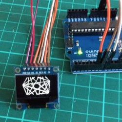
Dieser Post zeigt den Anschluß und Betrieb eines einfachen, weißen 0,96″ Zoll OLED Displays (eBay) mit SSD1306 Driver Chip und sieben Anschluss-Pins an einen Arduino Uno. Nano, und alle weiteren Modelle mit ATmega328 Pinout, dürften auf dieselbe Weise angesteuert werden können. Im Zweifel das Datenblatt des Arduinos zu Rate ziehen.
Im folgenden Video ist das OLED im Einsatz zu sehen. Die Chord-Animation ist von Hari Wiguna, sein Kode steht auf GitHub bereit.
Um ein OLED erfolgreich ansteuern zu können, ist die richtige Verdrahtung zwischen Arduino und Display wichtig. Dabei wird es durch die Tatsache, dass die Displays mit unterschiedlicher Anzahl und Beschriftung der Pins geliefert werden nicht einfacher. Die Libraries erlauben üblicherweise die Verwendung von Software oder Hardware SPI, wobei letztere Variante deutlich schneller ist. Hardware SPI erfordert mehr Anschluss-Pins als Software SPI.
| OLED Anschluss | Arduino PIN | Was ist das? |
|---|---|---|
| GND | GND | Ground |
| VCC | 5V | Volle Power! 🙂 |
| D0 | 13 | CLK, SCL, Hardware SCK |
| D1 | 11 | DATA, MOSI DATA, SDA, Hardware MOSI |
| DC | 6 | Data/Command |
| DS | 7 | CS, Chip Select |
| RES | 8 | Reset |
Das im Video gezeigte 0,96″ Display ist zur Ansteuerung durch Hardware SPI entsprechend der Tabelle mit dem Arduino zu verbinden. Bitte unbedingt prüfen, ob das eigene Display für 5V ausgelegt ist! Im Zweifel am 3,3V Pin anschließen und erst einmal damit versuchen. Die “Was ist das?”-Spalte in der Tabelle zeigt die ausgeschriebenen, gängigen oder alternativen Bezeichnungen der Anschlüsse; vielleicht hilft es dem einen oder anderen bei der Verkabelung. Ich fand diesen Beitrag von paulwb im Adafruit-Forum sehr hilfreich, um das Display nach einigen erfolglosen Versuchen endlich zum Laufen zu bringen.
Hier noch der Arduino-Sketch zur Darstellung der Animation wie im Video.
#include
#include
#include
#include

/* Wiring for Hardware SPI
    GND ------- ground
    VCC ------- 5V
    D0 -------- 13 hardware SCK
    D1 -------- 11 to hardware MOSI
    DC -------- 6 (user choice, defined below)
    DS -------- 7 (user choice, defined below)
    RST ------- 8 (user choice, defined below)
  Hardware MISO (12) unused */

#define OLED_DC     6
#define OLED_CS     7
#define OLED_RESET  8
Adafruit_SSD1306 display( OLED_DC, OLED_RESET, OLED_CS );

void setup( ) {
  display.begin( );
  display.clearDisplay( );
  display.display( );
}

int nFrames = 36;
void loop() {
  for ( int frame = 0; frame < nFrames; frame++ )
    HariChord( frame );
  for ( int frame = ( nFrames - 1 ); frame >= 0; frame-- )
    HariChord( frame );
}

void HariChord( int frame ) {
  display.clearDisplay( );
  int   n   = 7;
  int   r   = frame * 64 / nFrames;
  float rot = frame * 2 * PI / nFrames;
  for ( int i = 0; i < ( n - 1 ); i++ ) {
    float a  = rot + i * 2 * PI / n;
    int   x1 = 64 + cos( a ) * r;
    int   y1 = 32 + sin( a ) * r;
    for ( int j = i + 1; j < n; j++ ) {
      a  = rot + j * 2 * PI / n;
      int x2 = 64 + cos( a ) * r;
      int y2 = 32 + sin( a ) * r;
      display.drawLine( x1, y1, x2, y2, WHITE );
    }
  }
  display.display( );
}
Zugriff auf Photo Stream Bilder auf dem Mac ohne Photos App
Der Use Case: Mit dem iPhone, iPad oder iPod geknipste Bilder können über die sog. “My Photo Stream”-Funktionalität automatisch auf die jeweils anderen, verbundenen Geräte übertragen werden. Das ist praktisch. Es wäre aber noch praktischer, wenn diese Bilder ebenso automatisch auf den Mac synchronisiert würden. Das ist möglich, erfordert aber ein paar Handgriffe. Insbesondere, wenn man eine Lösung sucht, bei der man nicht die Photos App verwenden möchte und die Bilder in einem beliebigen Zielordner landen sollen. Hier das Vorgehen, inspiriert durch einen Artikel auf bockenhauer.com, den es dort allerdings nicht mehr gibt.
Wie funktioniert’s?
Wir schalten sowohl auf dem gewünschten mobilen Gerät, also iPhone, iPad oder iPod, als auch auf dem Mac die “My Photo Stream”-Funktion ein. Danach landen alle mit dem mobilen Gerät aufgenommenen Bilder sowohl (und wie bisher) im “Camera Roll”-Ordner und (neu) zusätzlich in einem Ordner mit dem Namen “My Photo Stream”. Zeitgleich werden die Bilder auf alle verbundenen Geräte in deren “My Photo Stream” Ordner gespiegelt. Beim Mac gibt es aber einen solchen Ordner nicht. Stattdessen werden die Photo Stream Bilder in einen Unterordner des Photos App Packages gelegt. Die hier beschriebene Lösung greift auf diesen Ordner zu und verschiebt die Bilder in einen Wunsch-Zielordner.
My Photo Stream auf dem Mac
Eine kurze Schritt-für-Schritt-Anleitung, um einen “My Photo Stream”-Ordner auf dem Mac zu emulieren.
- Photo Stream einschalten. Das ist an vielen anderen Stellen im Netz schon detailliert beschrieben, bspw. hier. Die Kurzversion für’s iPhone: Settings → iCloud → Photos → “My Photo Stream” einschalten. Und für den Mac: System Preferences → iCloud → dort rechts bei Photos den Options-Button klick → “My Photo Stream” einschalten. Kann man alternativ auch über die Settings der Photos App einschalten, aber viele Weg, Rom, etc. pp. NB: Weder “iCloud Photo Library” noch “iCloud Photo Sharing” müssen eingeschaltet sein, damitdie hier beschriebene Lösung funktioniert.
- exiv2 installieren, falls noch nicht vorhanden. Die Lösung setzt zum Umbenennen der jpeg-Dateien auf Basis der im jpeg-Header (hoffentlich) vorhandenen EXIF-Informationen auf
exiv2. Das Tool lässt sich einfach via (home)homebrew installieren, und zwar so:$ brew install exiv2
Wenn der Packet-Managerbrewnoch nicht vorhanden ist, dann natürlich erst einmal homebrew installieren… - Shell Datei anlegen. Das folgende Shell-Skript den eigenen Bedürfnissen anpassen und dann in einem Verzeichnis bspw. als
photostream.shspeichern.#!/bin/bash # Alle Photo Stream Bilder in den Ordner ~/Downloads/MyPhotoStream/_tmp kopieren find ~/Pictures/Photos\ Library.photoslibrary/Masters/ -type f -exec cp "{}" ~/Downloads/MyPhotoStream/_tmp/ \; # in das _tmp Verzeichnis wechseln cd ~/Downloads/MyPhotoStream/_tmp # Mit dem Programm exiv2 das Aufnahmedatum aus den EXIF-Daten jeder jpg-Datei auslesen. # Der Parameter -t setzt das modification date der Dateien auf ihr Aufnahmedatum. # Der Parameter -r benennt die Dateien um: Es wird dem Dateinamen das Aufnahmedatum im ISO8601-Format vorangestellt. /usr/local/bin/exiv2 -t -r'%Y%m%d_ :basename:' rename $(ls) # Die Bilder aus dem aktuellen _tmp Verzeichnis in das darüberliegende "MyPhotoStream" Verzeichnis verschieben find . -type f -exec mv "{}" .. \; # Abschließend die Bilder aus dem Photostream-Ordner löschen rm -r ~/Pictures/Photos\ Library.photoslibrary/Masters/* rm -r ~/Pictures/Photos\ Library.photoslibrary/Thumbnails/* - photostream.sh Rechte setzen. Mit
$ chmod 700 photostream.sh
die Rechte der Shell-Datei auf “ausführbar” setzen. - Automatisieren. Wir richten einen Daemon ein, der einmal pro Minute unser
photostream.shSkript aufruft. Auf diese Weise werden Bilder-Neuankömmlinge aus dem Photo Stream regelmässig und zeitnah aus dem Photos App Unterordner in unseren Zielordner überführt. Dazu wird eine Datei mit folgendem Inhalt an einem beliebigen Ort mit dem Namencom.NAME.photostream.plistangelegt. NAME kann frei gewählt werden.Label com.NAME.photostream ProgramArguments /Volumes/Macintosh HD/Users/USER/photostream.sh StartInterval 60 In der Datei ist NAME in<string>com.NAME.photostream</string>entsprechend des beim Anlegen der Datei gewählten Dateinamens zu ändern. Auch der Pfad/Volumes/Macintosh HD/Users/USER/photostream.shmuß so angepasst werden, dass er korrekt auf diephotostream.shShell-Datei zeigt. DasStartIntervalvon 60 entspricht 60 Sekunden, d.h. das Skript wird einmal pro Minute aufgerufen. Wer weniger häufig nach neuen Bildern im Photo Stream nachschauen möchte, kann den Wert einfach nach oben setzen. - Daemon aktivieren. Wir müssen dem Daemon/Agent manager
launchdnoch mitteilen, dass es einen neuen Daemon gibt, um den er sich kümmern soll. Das geschieht auf der Kommandozeile mit dem folgenden Befehl:$ launchctl load com.NAME.photostream.plist
Auch hier ist NAME entsprechend zu ersetzen.
Fertig! Wenn’s erstmal läuft, läuft’s wie geschnitten Brot. Auch mit El Capitan und ohne AirDrop. 😉
Chrome Shortcut oder Tastenkombination um aktuelles Tab zu duplizieren
Der übliche Weg, um ein Tab in Chrome zu duplizieren führt über einen Rechts-Klick auf das Tab und Auswahl des Popup-Menüpunktes “Duplicate”.
Wer als Tastatur-Universalhackspecht seine Finger aber lieber auf dem Keyboard belassen möchte, findet jeden Griff zur Maus nervig. Leider gibt es in Chrome keine eingebaute Tastenkombination, um das aktuelle Tab zu duplizieren.
Eine schnelle Variante, die allerdings kein 100%iges Duplikat erzeugt: CMD+L (aktiviert die URL-Zeile), dann CMD+Return. Zack! Schon wird das Tab geklont. Aber nur geklont, nicht echt dupliziert. Die Seite wird neu geladen, was beim Duplizieren nicht der Fall sein sollte. Weder die Position im Dokument noch die History (Back-Button) wird übertragen. Wer damit leben kann, ist mit dieser Lösung axellent bedient. Weitere Lösungsvorschläge im Geek TV Style liefert dieser Stackoverflow-Post.
Zweite Variante, ohne Hacken: Die Chrome Extension Duplicate Tab Shortcut Key installieren. So muß ‘ne Extension aussehen, dann klappt’s auch mit dem Nachbarn Duplizieren.