
Sonoff Basic: Tasmota Firmware flashen und mit Alexa verbinden
Das braucht man.
- 1 x Sonoff Basic, bspw. das oder das.
- 1 x FTDI Modul FT232RL, bspw. so eins hier.
- 1 x Stiftleiste mit vier Kontakten
- 4 x Female/Female Drähte
Vorbereiten des Sonoff Basic
- Sonoff Platine Mit einem Schraubendreher oder dem Fingernagel vorsichtig den Boden vom Gehäuse ablösen. Dann die Platine entnehmen. Die ist nur eingelegt und nicht verschraubt.
- Stiftleiste anlöten Oben rechts des kleinen gelben Trafos und über dem Taster (vgl. rote Markierung im Bild) befinden sich vier Lötpunkte. Dort eine Stiftleiste anlöten. Tipp: Die Stiftleiste vor dem Löten mit etwas Sekundenkleber auf der Vorderseite fixieren. Dann fällt sie beim Umdrehen nicht raus. Gelötet wird ja auf der Unterseite.

NB: Wer geschickt ist, spart sich das Löten und nimmt statt der Female/Female Drähte vier Male/Female Drähte und steckt die Male-Pins direkt in die Löcher auf der Platine. Durch Schrägstellung der Pins kann man auf diese Weise Kontakt mit den durchgeloteten Löchern herstellen. Ist mir zu frickelig, daher habe ich eine Stiftleiste angelötet.
Vorbereiten des FTDI Moduls
- 3,3V Die meisten FTDI Module erlauben es über einen Jumper oder eine Lötbrücke, die Pegelspannung auszuwählen: Entweder 5V oder 3,3V. Für den Sonoff Basic sind 3,3V die richtige Wahl. Mit 5V kann es Rauchwolken geben. Also unbedingt das FTDI Modul auf 3,3V Pegelspannung einstellen!
- Kabelage an FTDI Modul anschließen Es ist für das spätere Flashen sehr hilfreich, wenn die vier Kabel-Adern zuvor in der richtigen Reihenfolge am FTDI Modul angeschlossen wurden. Auf meinem Sonoff Basic sind die vier Anschlüsse von links nach rechts: 3.3V, Tx, Rx, GND. Die sechs Anschlüsse des FTDI Moduls, von links nach rechts: GND, o, VCC, Rx, Tx, o. NB: Die mit “o” bezeichneten Anschlüsse werden nicht benötigt.
              3,3V    Tx     Rx     GND--+
               |      |      |           |
               |      |      |           |
               |      |      |           |
GND     o     VCC     Rx     Tx     o    |
 |                                       |
 +---------------------------------------+
3,3V vom Sonoff werden mit VCC des FTDI-Moduls verbunden. GND (=Masse) mit GND. Man könnte meinen, dass Tx mit Tx und analog Rx mit Rx verbunden werden müssten. Dem ist aber nicht so: Tx steht für Transmit, Rx für Receive. Wenn das FTDI Modul via Tx etwas sendet, dann muss es von der Sonoff Platine via Rx empfangen werden. Und umgekehrt. Daher die Verdrahtung wie hier gezeigt.
Software, die für’s Flashen benötigt wird.
- NodeMCU PyFlasher Den NodeMCU PyFlasher hier runterladen. Gibt’s sowohl für den PC als auch den Mac.
- Tasmota firmware Aus dem Tasmota github repo die aktuellste Version der Firmware runterladen. Da stehen eine ganze Menge verschiedener Binärdateien zum Download bereit. Welche nehmen? Wer weder WPS noch SmartConfig noch Programm-Kode für Sensoren braucht, der wählt
tasmota-lite.bin(ehemalssonoff-basic.bin). Alternativtasmota-DE.bin, wer als Sprache deutsch möchte. Der Sonoff Basic Wifi Smart Switch hat keine Sensoren an Board, daher brauchen wir in der Firmware auch keinen Kode für Sensoren(abfragen). SmartConfig funktioniert nur im Zusammenspiel mit einer Android-App. Und WPS für die Verbindung mit dem WLAN ist auch nicht zwingend notwendig. Daher war alsotasmota-lite.binfür mich die richtige Wahl.
Flash, ahaaaa, saviour of the Universe! Jetzt wird die Tasmota Firmware auf den Sonoff Basic geflashed!
- FTDI Modul an Mac/PC anschließen Das FTDI Modul per USB Kabel mit dem Mac/PC verbinden. Meistens leuchtet irgendeine LED auf dem Modul, dann hat das Dingen Strom. Beim ersten Anstecken kann es sein, dass noch eine Treiber-Software installiert werden muss. Das sollte Euer Betriebssystem automatisch erledigen. Jetzt ist das Modul einsatzbereit.
- NodeMCU PyFlasher Den NodeMCU PyFlasher starten und konfigurieren: Zunächst den Serial Port auswählen. Auf dem Mac ist das sowas wie cu.usbserial-xxxx, auf dem PC ein COM-Port. Dann bei “NodeMCU firmware” mit dem Browse-Button die zuvor runtergeladene Tasmota Firmware Datei auswählen. Die Baud rate muss auf 115200 eingestellt werden. Der Flash Mode ist abhängig vom Sonoff Modultyp; für den Basic ist DOUT die richtige Wahl. Abschließend “Erase flash” auf yes setzen. Damit ist der PyFlasher fertig konfiguriert.

- Flashen Zum Flashen wie folgt vorgehen: Den Taster auf der Sonoff Platine drücken und gedrückt halten. Während dieser gedrückt ist, dass vieradrige vom FTDI-Modul kommende Kabel mit seinen vier Buchsen auf die eingelötete Stiftleiste der Sonoff-Platine aufstecken. Einen Moment warten und erst dann den Taster loslassen. Damit ist die Sonoff Platine im Flash-Modus. Jetzt im PyFlasher den Button “Flash NodeMCU” anklicken. Der Flash-Vorgang sollte starten und sich nach nicht allzu langer Wartezeit mit einem “Firmware successfully flashed.” zurückmelden.
- Neustart Die Drähte von der Stiftleiste des Sonoff abziehen und wieder verbinden. Wenn jetzt die grüne LED blinkt, hat alles geklappt. Wahrscheinlich.
Den Sonoff mit dem heimischen WLAN verbinden.
- Die LED blinkt Das Blinken der LED zeigt an, dass der Sonoff Basic nun versucht sich mit einem WLAN Netzwerk zu verbinden. Noch kennt er aber weder den Namen des eigenen WLANs noch dessen Passwort. In diesem Zustand spannt der Sonoff Basic einen eigenen Access Point auf. Den brauchen wir im nächsten Schritt.
- Mit Sonoff per WLAN verbinden Um dem Sonoff Name und Passwort des eigenen WLANs mitzuteilen, müssen wir uns erst mit dem WLAN Netzwerk, dass er selber aufspannt, verbinden. Also über die Netzwerk-Einstellungen vom Mac oder PC mit dessen WLAN, das irgendwie “sonoff-XXXX” heißt, verbinden.
- 192.168.4.1 Je nach Betriebssystem öffnet sich nun ein Browser-Fenster, in dem die Zugangsdaten des eigenen WLAN Netzwerkes eingegeben werden können. Sollte sich kein Fenster öffnen, dann einfach im Browser die IP-Adresse
192.168.4.1eingeben.
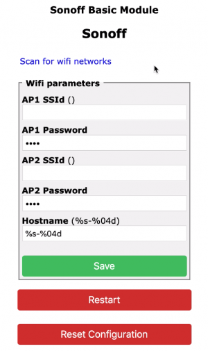 In der Regel wird es genügen, den Namen des eigenen Netzwerkes im Feld “AP1 SSId” und das zugehörige Passwort im Feld “AP1 Password” einzugeben. Nach Klick auf den Save-Button werden die Einstellungen im Sonoff gespeichert und dieser neu gebootet.
Und das war’s. Nach dem Reboot sollte sich der Sonoff Basic Wifi Smart Switch automatisch mit dem heimischen Netzwerk verbinden. Leider kann man dem Sonoff nicht ansehen, ob er sich denn auch erfolgreich mit dem eigenen WLAN verbunden hat. Mit der IP-Adresse 192.168.4.1 kann man den Sonoff jetzt nicht mehr ansprechend, da das vom Sonoff aufgespannte eigene “sonoff-XXXX” Netzwerk nicht mehr existiert. Vorausgesetzt, die Verbindung zum eigenen WLAN Router war erfolgreich, dann hat der Sonoff jetzt eine andere vom WLAN Router per DHCP vergebene IP-Adresse. Wenn wir diese kennen, können wir sie im Browser eingeben und auf die Konfigurationsoberfläche des Sonoff gelangen. Aber wo bekommen wir diese IP-Adresse her? Hier zwei mögliche Wege.
- Liste verbundener Geräte Wenn man sich in die Admin-Oberfläche seines WLAN Routers einwählt, kann man üblicherweise (irgendwo) eine Liste der mit diesem Router verbundenen Geräte einsehen. Und genau in dieser Liste müsste auch der Sonoff Basic zu finden sein. Manche Geräte und/oder Hersteller werden von den WLAN Routern erkannt und mit Namen ausgewiesen, das vereinfacht die Suche. In meinem Router wird der Sonoff Basic nicht benamt, daher kann es mitunter nötig sein, verschiedene der angezeigten IP-Adressen im Browser einzugeben, bis man die richtige gefunden hat.
- Terminal Programm Wenn der Sonoff Basic mit dem FTDI Modul verbunden ist, kann man mit einem Terminal-Programm direkt auf den Sonoff zugreifen. So lassen sich Parameter auslesen oder der Sonoff über eine Vielzahl an Kommandos konfigurieren; im Tasmota-Github sind alle verfügbaren Kommandos gelistet.
Für den PC wird als Terminal-Programm gerne das kostenlose Termite benutzt. Für den Mac gibt es bspw. das ebenfalls kostenlose CoolTerm. Im Terminal-Programm muss zunächst der Port ausgewählt werden über den das FTDI Modul mit dem PC/Mac verbunden ist, also COMx oder cu.usbserial-xxxx. Dann noch die Baud rate auf 115200 setzen und, im Falle von CoolTerm, den Line Mode einschalten. Dann ggfs. mit dem Sonoff verbinden (bspw. via “Connect” o.ä.) und wir sollten Zugriff auf die Tasmota Firmware auf dem Sonoff Basic haben.
Als ersten Test im Terminal-Programm den Befehl “status” gefolgt von Return eingeben. Wenn dann etwas im Terminal-Programm ausgegeben wird, hat die Verbindung geklappt!
Jetzt wollen wir die IP-Adresse herausbekommen. Mit dem Befehl “restart 1” wird der Sonoff gebootet. Und dann sollten Informationen im Terminal ausgegeben werden, u.a. die IP-Adresse, mit der der Sonoff mit dem WLAN verbunden ist; vgl. Screenshot.

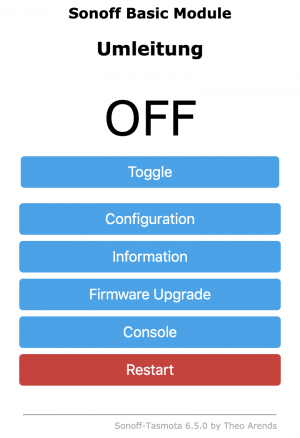
Jetzt kennen wir die IP Adresse und können diese in der Adress-Zeile unseres Browsers eingeben. Dort sollte uns dann der Startbildschirm des Sonoff Basic begrüßen.
Fertig! Nun kann man den Sonoff Basic Wifi Smart Switch bspw. über den Browser eines Handys steuern. Oder auf einem Android-Gerät eine passende App dafür installieren. Oder den Switch ins heimische Home Automation Netz einbinden.
Oder ihn per Alexa steuern. Wie das geht, zeige ich in meinem Sonoff Basic: Tasmota Firmware flashen und den Wifi Smart Switch mit Alexa verbinden HD Video auf YouTube.
Viel Spaß!

7 easy steps to set up OctoPrint on Raspberry Pi
If you want to remotely control your 3D printer, OctoPrint might be your choice. This is a very, very short seven-step instruction to show, how OctoPrint is set up on a Raspberry Pi. No pictures, no videos, just the plain vanilla facts.
- Download Octoprint from octoprint.org.
- Flash Octoprint image Use, e.g., Etcher from balena to flash the Octoprint image on a micro SD card. Do not format the SD card even if your operating system asks you to do so. Just flash the Octoprint image on the SD card.
- Setup Wifi Re-insert the SD card in your SD card reader. Edit the file
octopi-wpa-supplicant.txtin theboot/directory. Use an appropriate editor to do this. There is a plethora of information out there that explains why this is important; in case of doubt please use a search engine.
There are two sections in the file that are relevant:### WPA/WPA2 secured #network={ # ssid="" # psk=" " #} # Uncomment the country your Pi is in ... #country=GB # United Kingdom #country=CA # Canada #country=DE # Germany #country=FR # France country=US # United States Take care that you uncomment the country you’re living in and comment out the one that was previously uncommented. Take even more care that you do not only enter the ssid and your password in the WPA/WPA2 section but that you also uncomment the lines starting from
networkdown to and including the line with the single closing brace. - Enable SSH To log into your Pi via SSH you may need to enable it first. Do this bei putting an empty file named
ssh(without any extension) in theboot/directory (if it does not exist already, of course). A simple way to create an empty file is to use the following commandtouch ssh. - Fire up the Octopi Put the SD card into your Pi, connect a power source and fire it up! Wait approx. 90 seconds until the boot process is completed.
- Log in using SSH Use ssh to remotely log into your Pi*. The Octopi will be reachable either by using its IP address (that you will have to find out, e.g., by looking into your router’s attached devices section) or via
octopi.local. The latter requires Bonjour to run properly on your computer. Assumed you know the IP address, use this terminal command to log in:
SSH pi@<ip-address>
You will be asked to confirm a certificate. Type ‘yes’ followed by a return. Then enter the password. The standard password israspberry.
(*Mac users will usually use terminal, Windoze users may want to use PuTTy as a SSH-client.) - Change password Change the standard password using the command
passwd. You will be asked to enter the old password then twice the new one. Done. - Access OctoPrint via web browser Start a web browser and enter
http://octoprint.local(requires Bonjour service) orhttp://<ip_address>. You should see the OctoPrint interface and a setup wizard pop up. This page has a table with settings for many common 3D printers. Follow along and be sure to set up a username and password for your OctoPrint.
Now open up the connection panel on the left. With the options set to “AUTO” hit Connect. If the connection was successful congratulations – you’ve successfully set up OctoPrint!
Optional steps.
- Static IP Out-of-the-box, your Pi will receive a dynamic IP address. I prefer to have a static IP address.
When the Pi is booted and you are logged in, use the following command on the command line to edit the dhcpcd.conf file:
sudo nano /etc/dhcpcd.conf
Go to the section that looks similar to the following lines…interface wlan0 static ip_address=
static routers= static domain_name_servers=8.8.4.4 8.8.8.8 …and enter your desired IP address, your router’s IP address, and, optionally, your preferred domain name server(s). The ones above are the Google DNSs. Use
sudo rebootto reboot the Pi. - Full upgrade Consider a full upgrade of your intallation by issuing the following command on your terminal.
sudo apt update && sudo apt full-upgrade -y
That could take quite some time.
MacOS Finder: Spaltenreihenfolge dauerhaft ändern
Die Reihenfolge der Spalten im MacOS Finder lässt sich einfach durch drag’n’drop den eigenen Bedürfnissen anpassen. Es ist jedoch zu beachten, dass sich die geänderte Reihenfolge stets nur auf das aktuelle Verzeichnis bezieht. Soll die aktuelle Reihenfolge für alle Ordner gelten, so ist der View Options Dialog via CMD + J zu öffnen und nach dem Ändern der Reihenfolge unten der Button “Use as Defaults” zu drücken.
Aber: Das reicht in der Regel nicht! MacOS merkt sich Ordner-spezfifische Einstellungen in der, in jedem Ordner vorhandenen, Datei .DS_Store. Und die in dieser Datei hinterlegten Einstellungen haben Vorrang vor den globalen Einstellungen, die via “Use as Defaults” eingestellt wurden (selbige werden in com.apple.finder.plist abgelegt, just for the Nerds).
Das Vorgehen, das bei mir zu dauerhaftem Erfolg geführt hat, ist wie folgt:
- Reihenfolge der Spalten im Finder anpassen.
CMD + Jund dann “Use as defaults”.- Im Terminal
sudo find /Users/<username>/ -name .DS_Store -deleteeingeben, Return. Dies löscht alle(!).DS_StoreDateien in allen Verzeichnissen. ACHTUNG! Eine Falscheingabe dieses Befehls kann zu ernsthaften Schäden am System führen. Wer nicht weiß, wie dieser Befehl funktioniert und was da genau passiert, BITTE LASSEN. - Finder neu starten: Entweder im terminal mit
killall Finderoder mit Alt + Rechtsklick auf das Finder-Icon im Dock und dort dann “Relaunch” wählen.
Hernach sollten vom Finder alle Verzeichnisse mit den Spalten in der gewünschten Reihenfolge anzeigen.

How to convert 3MF files to stl format on a Lin*x machine (including Mac)
If you need to convert a 3MF file to STL format you may find that there is no really simple solution. I found this very useful blog post by Zebethyal that describes how the command line tool 3mf2stl by Charles Shapiro can be compiled on a Mac to convert 3MF files to STL format. The required steps in all brevity:
- Install Homebrew
Open terminal and type (all in one line)
ruby -e "$(curl -fsSL https://raw.githubusercontent.com/Homebrew/install/master/install)" < /dev/null 2> /dev/null
Hit return. Homebrew is downloaded and installed. - Install libzip
Type
brew install libzip
After hitting return, the libzip library will be installed. - Download 3mf2stl
Enter the following URL in your browser
https://github.com/lemgandi/3mf2stl
and download the 3mf2stl repository (green button to the right, download as ZIP).
Unzip the file to a directory, e.g.~/Documents/3mf2stl/ - Compile 3mf2stl
Change to this directory
cd ~/Documents/3mf2stl/
and type
make
Hit return. The code will be compiled.
If the compilation was successful you will have an executable named 3mf2stl in this directory.
Usage is ./3mf2stl -i <input_file.3mf> -o <output_file.stl>
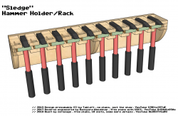
Plans: Hammer Holder “Sledgehammer”
 If you do not like the “standard” hammer holders then you might have come to the right place! These plans show how to build a really unusual hammer holder for your shop. It features a locking mechanism that keeps the hammers in place even in case of an earthquake (presumably).
I made a two-part-video showing how I built this thing. Here you can find part one on YouTube.
And here you can download the free plans for the hammer holder.
How to get rid of MacOS’ “one or more items can’t be changed because they are in use”
MacOS can be annoying, at times. In this case I was struggling with a video file that could not be copied, moved, or deleted because MacOS persistet on telling me it “can’t be changed because [it is] in use”; cf. this screenshot of the popup message.
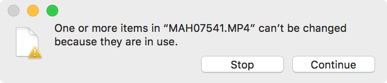
The Continue-Button might suggest that MacOS would perform the action if I clicked it. But after clicking continue, I was asked for my admin-password, the file would seemingly get copied (or moved etc.), and finally, the copied (or moved file etc.) would be deleted.
It took a lot of searching until I, finally, came across the solution in this thread. I did not dig into the gory details of the cause but it has something to do with the so-called extended file attributes. You can see if a file has extended file attributes when you do a ls in the terminal. If there is an @ on the right-hand side of the file permissions this file has extended attributes set. As was the case with my video file:
> ls
-rwxr-xr-x@ 1 zzz  staff  42164199 Dec 19 18:58 MAH07541.MP4
Using the -l@ flag we can see the extended attributes that are set for the file:
> ls -l@
-rwxr-xr-x@ 1 zzz  staff  42164199 Dec 19 18:58 MAH07541.MP4
	com.apple.FinderInfo	      32
So in my case it’s the com.apple.FinderInfo attribute that was causing the problem. As soon as I deleted the extended attribute using
> xattr -d com.apple.FinderInfo MAH07541.MP4
everything was back to normal and the file could be copied, moved, or deleted.
Be careful when you are fiddling with the extended attributes since they can also store resources or essential file metadata. A user in the above mentioned thread says that it is “…always safe to delete com.apple.FinderInfo”. Well, that is something you will have to decide on your own.
How to restart iPhone 8 (Plus|X) when you can’t shut down
The process of restarting your iPhone has changed with the advent of the iPhone 8, iPhone 8 Plus or iPhone X.
Such a restart, or hard reset, is necessary if your iPhone is acting weird like you are not able to shut it down by long pressing the side button or you can’t start apps etc.
The force-reboot is no longer achieved by pressing the side and home button simultaneously. Now you have to use the following sequence:
- Press the volume up button once.
- Press the volume down button once.
- Press and hold the side button until the Apple logo appears (approx. ten seconds).
That’s it, your iPhone should reboot. In case you protect your iPhone using a PIN, which is recommended, you will have to enter your PIN after reboot.

Webhosting (nicht nur) für echte Kommandozeilen-Nerds
Ich hab’ sie alle durch, die Massen-Web-Hosting-Anbieter. Eine nicht vollständige Liste in zufälliger Reihenfolge: Host Europe, all-inkl, Strato, Hetzner, alfashosting, goneo, GoDaddy, Celeros usw. usf. Das könnte ein langer, langer, geradezu ausgesprochen langer Rant darüber werden, was in schöner Regelmässigkeit bei denen alles nicht funktioniert bzw. funktioniert hat. Aber da muß jeder seine eigenen Erfahrungen machen. Und es ist auch gar nicht auszuschließen, dass jeder der genannten Dienstleister seine passende Zielgruppe hat, für die alles, sagen wir mal, irgendwie und gefühlt läuft.
Für mich war jeder Webhoster-Wechsel immer mit der Hoffnung verbunden, nun jemanden gefunden zu haben, der sein Geschäft im Griff hat. Aber eigentlich gab es immer nur Variationen der bekannten Ärgernisse: Support mit durchwachsener Fachkenntnis, träge Reaktionszeiten, Standardformulierungen, Geschwindigkeitsprobleme und Security Issues. Gerade der letzte Hoster setzt mit seiner technischen Inkompetenz insbesondere im Bereich des Server Hardenings dem ganzen noch einmal eine unrühmliche Krone auf. Der Name sei nicht genannt denn hier soll niemand diskreditiert werden.
Ganz im Gegenteil: Ich möchte hier einen Webhosting-Anbieter hervorheben, nein, geradezu anpreisen, der mir über die letzten zwei Jahre extrem an’s Herz gewachsen ist. Und das nicht, weil ich besonders oft den Support gebraucht hätte. Das war nur einmal der Fall und es gab innerhalb von Minuten eine fachlich extrem versierte Antwort, die konkret auf mein Anliegen einging und sofort weiterhalf. Das allein hat beim Martyrium aus IVRs, bestenfalls halb gelesenen E-Mails und Antworten, die dann nur noch auf ein Viertel des ursprünglichen Anliegens eingehen, schon extremen Seltenheitswert.
Katze aus dem Sack: Es geht um uberspace.de. Aus meiner Sicht kein klassischer One-Klick-To-Happiness-Webhoster mit Klicki-Bunti-GUI, sondern eher was für technikaffine Maker, die den Umgang mit der Kommandozeile nicht scheuen. Man muß sicher kein Web-Guru oder Un*x-Admin sein, aber schonmal in der Shell gearbeitet zu arbeiten, hilft sicherlich bei der Einrichtung des eigenen Web-Space. Allein daran sieht man schon, dass uberspace irgendwie … anders ist. Positiv anders.
Ein anderes Beispiel: Wer auf der Kommandozeile seine Domains, Mail-User oder den SpamAssassin verwalten möchte, der braucht eine Dokumentation. Die gibt es in Form eines umfangreichen WIKIs, das meiner Meinung nach kaum Wünsche offen lässt. Und noch etwas fällt sofort auf, wenn man das WIKI oder auch die Webseite durchliest: Kompetenz pur. Und Überzeugung. Beispielsweise, was die Preise/Bezahlung anbelangt. Jeder entscheidet selber, wieviel er uberspace bezahlen möchte. Auch die Abhandlungen über den Verzicht auf die Lastschrift (bezahlt wird per Überweisung) oder ganz generell immer wieder die Erläuterungen, warum das Team von uberspace die Dinge so macht, wie sie sie machen, sind absolut lesenswert.
Es gibt kaum eine Text, eine Erläuterung oder sonst eine Stelle, an der ich nicht einen Haken machen könnte. Selbst im gerade durchforsteten Impressum gibt es wieder etwas, wovon sich andere Seitenbetreiber etwas abschneiden könnten. Die meisten klicken sich ihren Impressums-Sermon bei erecht24 oder sonst wo zusammen und klatschen dann diesen Text mit mehr oder weniger Verstand auf ihre Seite. Bei uberspace finden wir aber: “[…] In Sachen Linkhaftung sparen wir uns den sonst üblichen Disclaimer, der nach Meinung der meisten Juristen ohnehin keine Rechtswirksamkeit entfaltet. […]” Ita est!
Ich bin schlichtweg begeistert von uberspace und wünsche mir inständig, dass sie im Rahmen der eigenen Ansprüche und Wünsche prosperieren und damit allen, die einen wirklich richtig guten Webhosting-Dienstleister haben möchten, lange erhalten bleiben!
I18n: nullseite.de goes zeropage.io
The king is dead, long live the king!
I started my private blog Nullseite BOY 2008. Since then it experienced two rebrushes and got an accompanying offspring EOY 2015 – the zeropage. There is only so much spare time one can spent on blogging (and other stuff;-) so I decided to quit trying to curate two blogs at the same time. The Nullseite will diminish as I am in the process of migrating the most worthy Nullseite-Posts to the zeropage. This requires some tedious manual labour and will, thus, take some time. Stay tuned!

3D Model: Space Invaders Vent Duct
Space Invader styled 100 mm diameter vent duct cover. This remix incorporates the Thingiverse designs 1970493 and 1065143. It’s really just this: A retro game styled vent duct with a twist.